
Lifting device capable of positioning corner

A lifting device and corner technology, which is applied to chairs with vertically adjustable seats, other seating furniture, tables with variable table heights, etc., can solve the problems of automatic positioning and inconvenient use, and achieve simple structure and easy operation. convenient effect

Inactive Publication Date: 2009-08-12
SOUTHWEST JIAOTONG UNIV
View PDF7 Cites 0 Cited by
  • Summary
  • Abstract
  • Description
  • Claims
  • Application Information

AI Technical Summary

Problems solved by technology

For example, the patent No. 02250660.8 is the reinforced pneumatic lifting rod. When the lifting device needs to be rotated at a certain angle, it cannot be automatically positioned at the required rotating position, but requires the user to use additional force or devices to clamp and fix it. , very inconvenient to use

Method used


Image

  • Lifting device capable of positioning corner
  • Lifting device capable of positioning corner

Examples


specific Embodiment approach

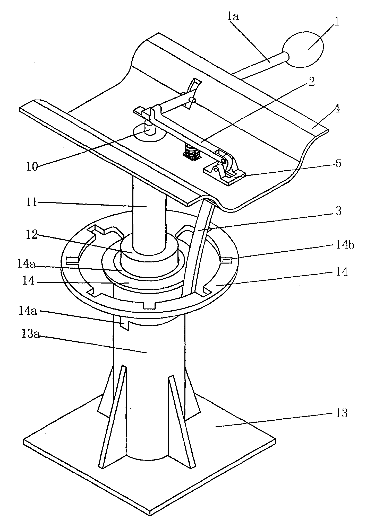
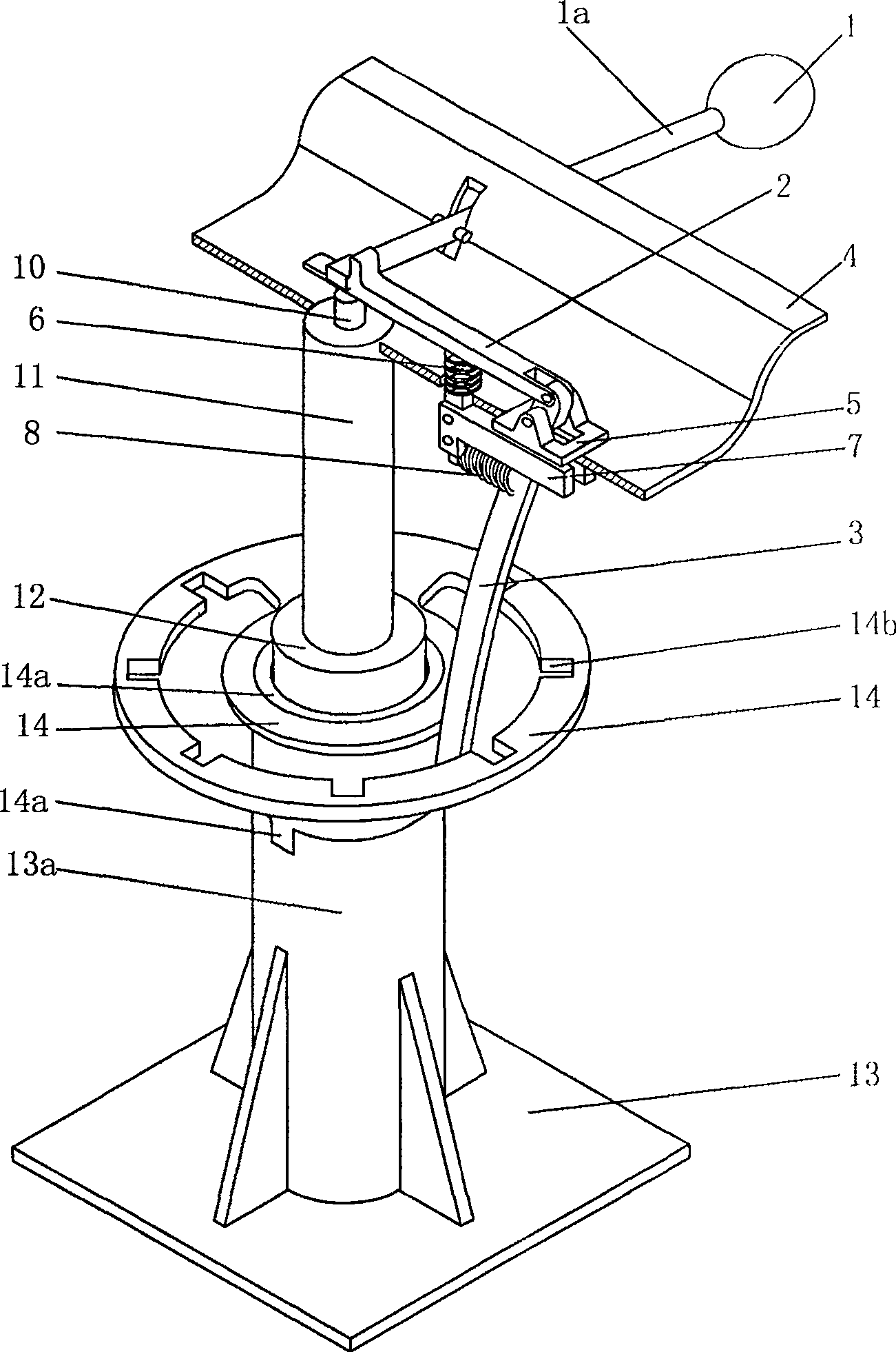
[0012] figure 1 , 2 Shown, a kind of specific embodiment of the present invention is:

[0013] A lifting device capable of locating corners, comprising a handle 1, a handle connecting rod 1a, a base plate 4, an activation rod 10, a piston rod 11, an outer cylinder 12, a base 13, one end of the handle connecting rod 1a and a push rod 2 on the base plate One end is fixedly connected, the other end of the push rod 2 has a U-shaped groove, and one end of the push rod 2 and the guide rod 3 are connected in a hinged manner in the U-shaped groove; the base plate 4 is provided with a hinge seat 5, and the guide rod 3 passes through the base plate 4 and hinged on the hinge seat 5 at the same time; the middle part of the push rod 2 is fixed with a tension spring 6, and the other end of the tension spring 6 passes through the bottom plate 4 and is connected with the end of the guide groove 7 below the bottom plate 4; the guide groove 7 The end is also connected with stage clip 8, and t...


PUM


Abstract

A lifting device capable of positioning corners, one end of the handle is fixedly connected to one end of the push rod on the base plate, the other end of the push rod is opened with a U-shaped groove, and the push rod and one end of the guide rod are hinged in the U-shaped groove There is a hinge seat on the bottom plate, and the guide rod passes through the bottom plate and is hinged on the hinge seat at the same time; the middle part of the push rod is fixed with a tension spring, and the other end of the tension spring passes through the bottom plate, and is connected with the fixed guide groove under the bottom plate. The ends are connected; the end of the guide groove is also connected with a compression spring, and the other end of the compression spring is connected with the guide rod passing through the guide groove; the outer cylinder is provided with a chuck and a chuck sleeve, and the chuck and the chuck sleeve interfere Cooperate, the chuck sleeve engages with the base cylinder, and both the chuck sleeve and the base cylinder are tightly clamped on the outer cylinder; the lower part of the base cylinder is fixed on the base; Compatible card slot. The lifting mechanism can realize the function of rotating and positioning while ensuring the lifting function, improves the performance of the lifting mechanism, has a simple structure, and is flexible and convenient to operate.

Description

technical field [0001] The invention relates to a lifting mechanism, in particular to a lifting device capable of positioning a corner. Background technique [0002] Existing rotatable lifting mechanism usually adopts pneumatic lifting device. For example, the patent No. 02250660.8 is the reinforced pneumatic lifting rod. When the lifting device needs to be rotated at a certain angle, it cannot be automatically positioned at the required rotating position, but requires the user to use additional force or devices to clamp and fix it. , very inconvenient to use. Contents of the invention [0003] The object of the present invention is to provide a lifting device capable of locating corners. The lifting mechanism can realize the function of rotating and positioning while ensuring the lifting function, and improve the performance of the lifting mechanism. It has a simple structure and is flexible and convenient to operate. [0004] The present invention solves its technical ...

Claims


Application Information

Patent Timeline
Patent Type & Authority Patents(China)
IPC IPC(8): A47C3/20A47C3/24A47B9/00A47B9/04
Inventor 于涛高宏力许明恒姚应峰谭强景国玺何常红
Owner SOUTHWEST JIAOTONG UNIV
Learn More