Eureka AIR delivers breakthrough ideas for toughest innovation challenges, trusted by R&D personnel around the world.

Metalloid cooker for electromagentic furnace

A non-metallic and induction cooker technology, applied in home appliances, kitchen appliances, applications, etc., can solve the problems of complicated operation, inability to heat non-metallic cookers, and inability to achieve precise control, so as to reduce the interference of cognitive factors and achieve precise control , the effect of simple structure

Inactive Publication Date: 2009-08-12
潘毅强
View PDF4 Cites 0 Cited by
  • Summary
  • Abstract
  • Description
  • Claims
  • Application Information

AI Technical Summary

Problems solved by technology

[0002] With the improvement of technology, people have higher and higher requirements for cooking utensils. The simple, convenient and environmentally friendly induction cooker has gradually replaced the general open flame cooker and has become a cooking tool that people pay more and more attention to. The existing induction cooker products are affected by their basic structure and heating. Due to the limitation of the principle, the water or food in the container can only be heated through stainless steel, iron and other metal utensils, and non-metallic cookware cannot be heated directly. To use non-metallic cookware, it needs to be fixed at a position close to the bottom of the cooker. Metal magnetic heating elements usually have poor heat transfer effect for non-metallic cookware and cannot accurately measure the temperature inside the cooker, so they can only be used for cooking operations with people on site. If automatic operations such as automatic stop of heating (ie, water (automatic shutdown after boiling) function, you can only use the timing shutdown function of the induction cooker, the operation is more complicated, and it is affected by human judgment factors, so it is impossible to achieve precise control

Method used


Image

  • Metalloid cooker for electromagentic furnace
  • Metalloid cooker for electromagentic furnace
  • Metalloid cooker for electromagentic furnace

Examples


Embodiment 1

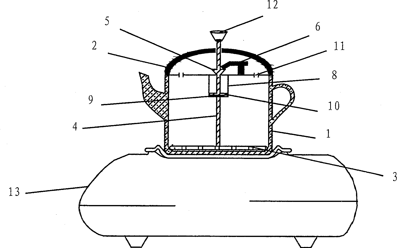
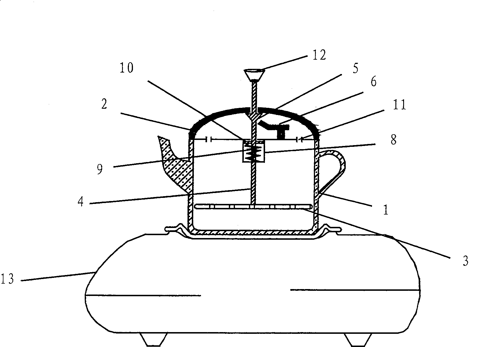
[0019] Embodiment 1: as figure 1 with 2 Shown, a kind of non-metal cooker for electromagnetic oven, comprises non-metal container 1 and the magnetic conduction heating body 3 that is arranged in this container, is provided with hollow cover 2 on the top of non-metal container 1, and the bottom of cover 2 is provided with There is a spring chamber 8 with a built-in compression spring 9. The magnetically conductive heating body 3 is provided with a central shaft 4 passing through the spring chamber 8 and extending out of the cover 2. A compression spring plate is provided on the central shaft 4 in the spring chamber 8. 10. The compression spring 9 is located between the compression spring plate 10 and the bottom of the spring chamber 8; a fixed pin 5 is provided on the central shaft 4 in the cover body 2, and a bimetallic pin 5 is provided on the inner bottom of the cover body 2 to cooperate with the fixed pin 5 A locator, the locator is a bimetal 6 with one end fixed on the in...

Embodiment 2

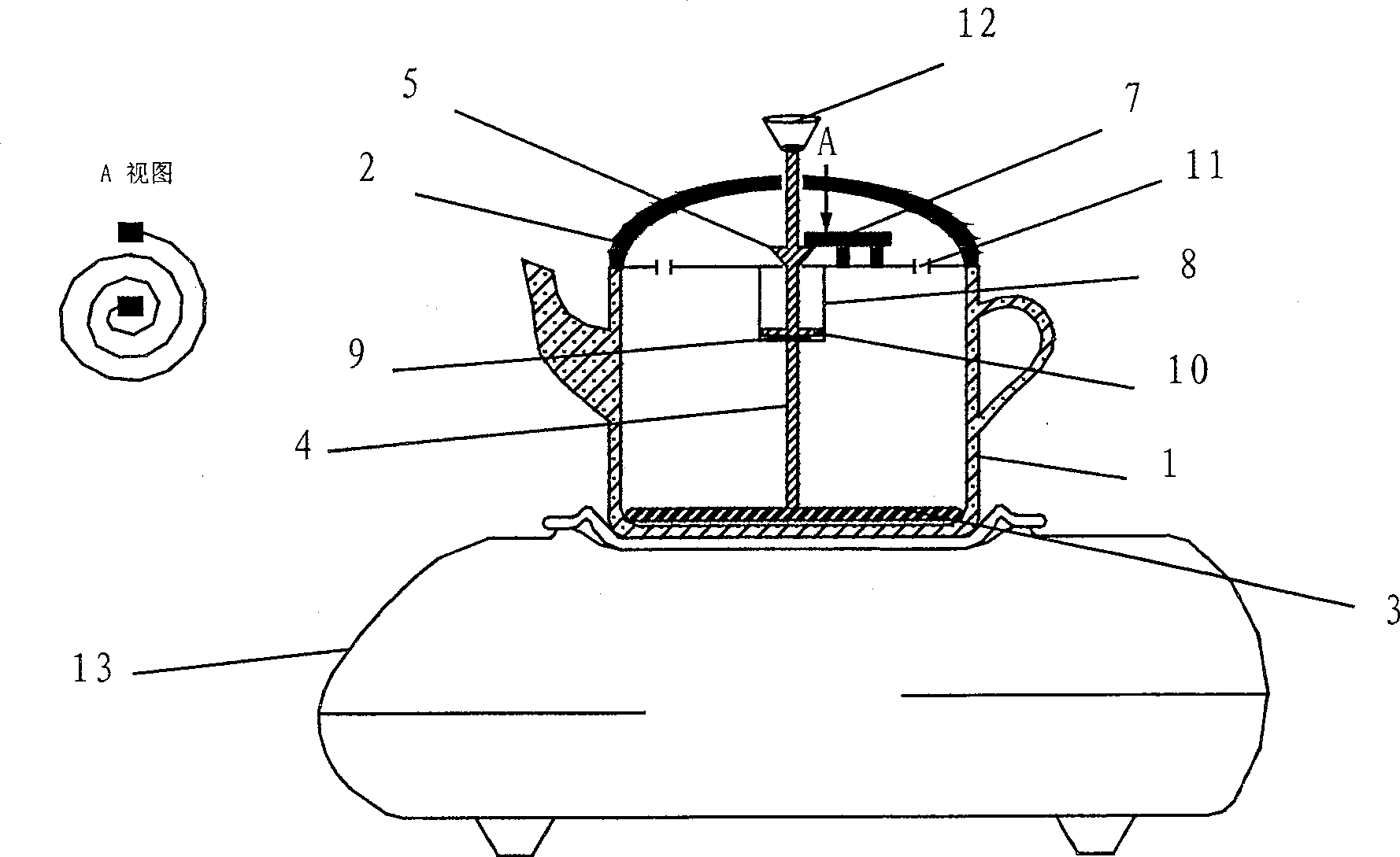
[0022] Embodiment 2: as image 3 with 4 Shown, a kind of non-metal cooker for electromagnetic oven, comprises non-metal container 1 and the magnetic conduction heating body 3 that is arranged in this container, is provided with hollow cover 2 on the top of non-metal container 1, and the bottom of cover 2 is provided with There is a spring chamber 8 with a built-in compression spring 9. The magnetically conductive heating body 3 is provided with a central shaft 4 passing through the spring chamber 8 and extending out of the cover 2. A compression spring plate is provided on the central shaft 4 in the spring chamber 8. 10. The compression spring 9 is located between the compression spring plate 10 and the bottom of the spring chamber 8; a fixed pin 5 is provided on the central shaft 4 in the cover body 2, and a bimetallic pin 5 is provided on the inner bottom of the cover body 2 to cooperate with the fixed pin 5 A locator, the locator is a bimetal coil spring 7 fixed at the bot...

Embodiment 3

[0025] Embodiment 3: as Figure 5 with 6 Shown, a kind of non-metal cooker for electromagnetic oven, comprises non-metal container 1 and the magnetic conduction heating body 3 that is arranged in this container, is provided with hollow cover 2 on the top of non-metal container 1, and the bottom of cover 2 is provided with There is a spring chamber 8 with a built-in compression spring 9. The magnetically conductive heating body 3 is provided with a central shaft 4 passing through the spring chamber 8 and extending out of the cover 2. A compression spring plate is provided on the central shaft 4 in the spring chamber 8. 10. The compression spring 9 is located between the compression spring plate 10 and the bottom of the spring chamber 8; a fixed pin 5 is provided on the central shaft 4 in the cover body 2, and a bimetallic pin 5 is provided on the inner bottom of the cover body 2 to cooperate with the fixed pin 5 A locator, the locator is a bimetallic curved sheet 14 whose two ...


PUM


Abstract

The invention discloses a non-metal cooker for an induction cooker, which comprises a non-metal container (1) and a magnetically conductive heating body (3) arranged in the container, and a hollow The cover (2), the cover (2) is fixed with an elastic piece, the magnetically conductive heating body (3) is provided with a central axis (4) that can be movably extended out of the cover (2), and the elastic piece The other end is connected to the central axis (4), and the central axis (4) in the cover (1) is provided with a fixed pin (5), and the inner bottom of the cover (2) is provided with a matching pin (5). In the bimetal locator, the cover (2) is provided with a steam guide hole (11) communicating with the inner cavity of the non-metal container (1). The invention has the advantages that the non-metal cooker can be used for heating in an electromagnetic oven, has a simple structure, is convenient to operate, can automatically stop heating, reduces the interference of human factors, and has precise control.

Description

technical field [0001] The invention relates to a non-metal cooker, in particular to a non-metal cooker used in an electromagnetic cooker. technical background [0002] With the improvement of technology, people have higher and higher requirements for cooking utensils. The simple, convenient and environmentally friendly induction cooker has gradually replaced the general open flame cooker and has become a cooking tool that people pay more and more attention to. The existing induction cooker products are affected by their basic structure and heating. Due to the limitation of the principle, the water or food in the container can only be heated through stainless steel, iron and other metal utensils, and non-metallic cookware cannot be heated directly. To use non-metallic cookware, it needs to be fixed at a position close to the bottom of the cooker. Metal magnetic heating elements usually have poor heat transfer effect for non-metallic cookware and cannot accurately measure the...

Claims


Application Information

Patent Timeline
Patent Type & Authority Patents(China)
IPC IPC(8): A47J27/00A47J36/06
Inventor 潘毅强
Owner 潘毅强
Why Eureka
Eureka Blog
Learn More