Rotor brake for a spinning rotor

A brake and rotor technology, applied in spinning machines, open-end spinning machines, continuous winding spinning machines, etc., can solve problems such as contact with the rotor, and achieve the effect of avoiding damage and eliminating sudden overload.

Inactive Publication Date: 2009-08-26
TEXPARTS GMBH
View PDF7 Cites 0 Cited by
  • Summary
  • Abstract
  • Description
  • Claims
  • Application Information

AI Technical Summary

Problems solved by technology

In this braking force introduction, which is separate from the opening of the housing part, there is a risk of possible contact with the still running rotor

Method used


Image

  • Rotor brake for a spinning rotor
  • Rotor brake for a spinning rotor
  • Rotor brake for a spinning rotor

Examples


Embodiment Construction

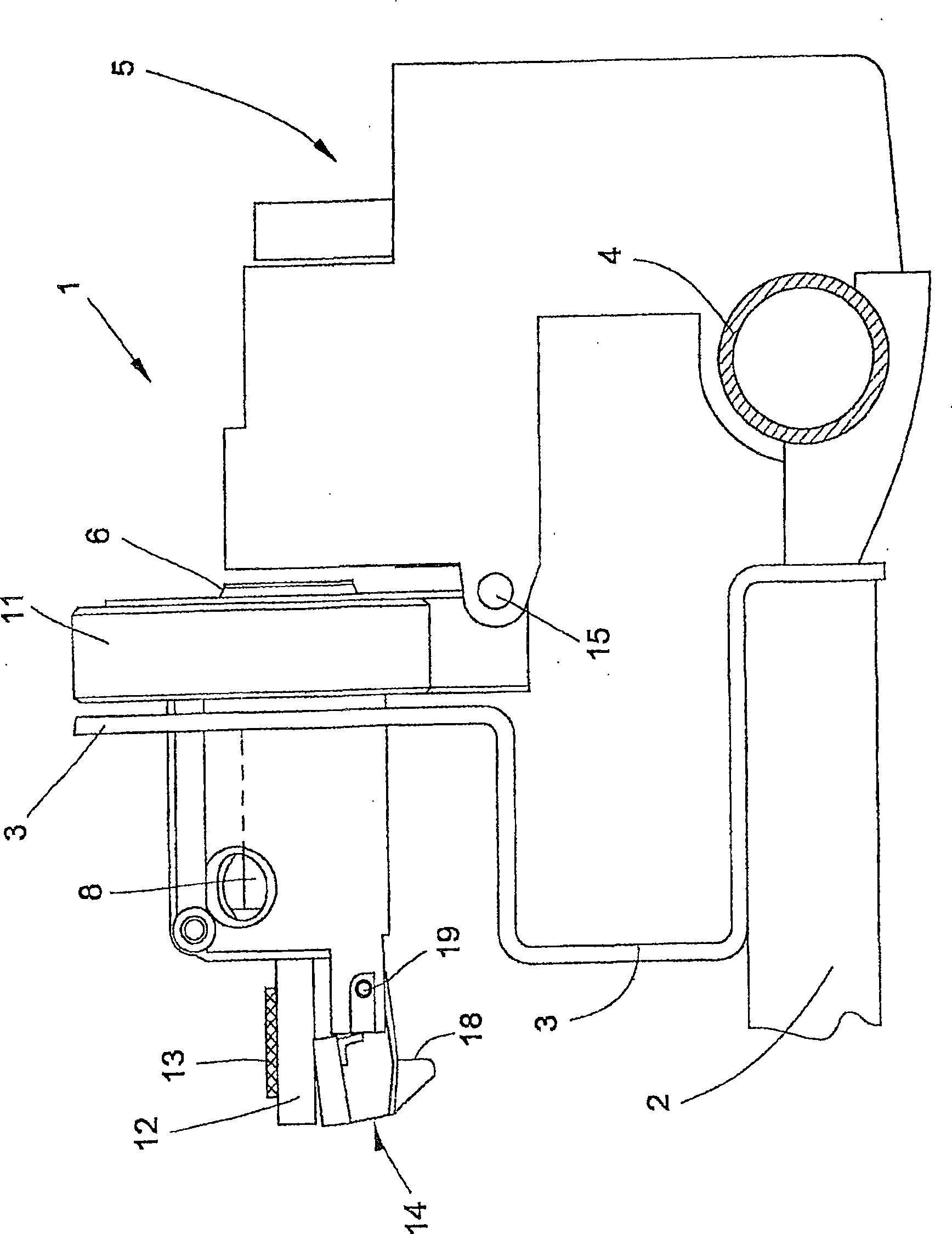
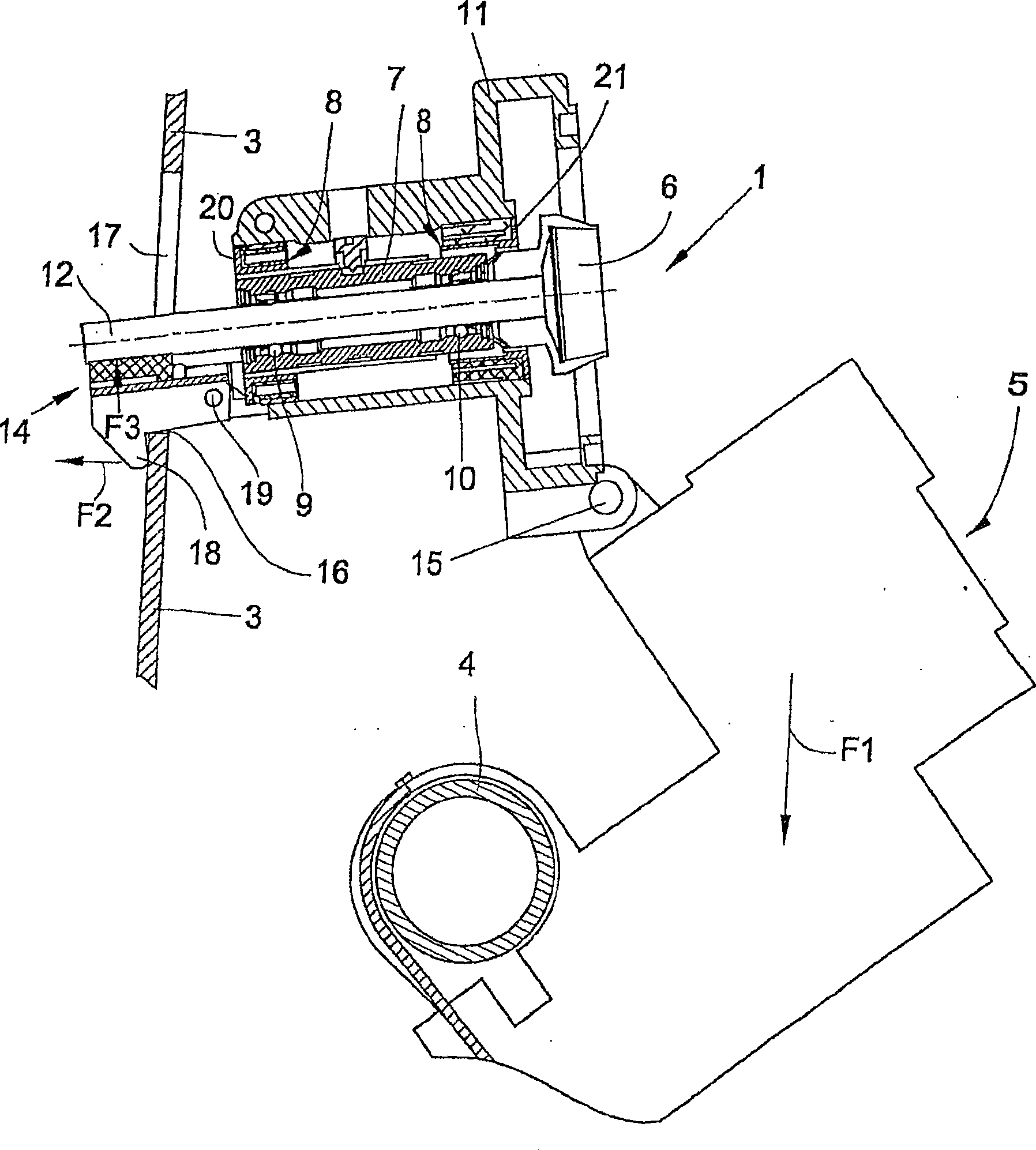
[0022] figure 1 with figure 2 Shows a well-known spinning tank 1. The carrier plate 3 and the pivot tube 4 are fastened to the beam 2 of the rotor spinning machine as part of the frame. The cover 5 includes structural members for fiber supply, fiber opening and fiber feeding to the spinning rotor 6, which are not shown in detail in the drawings. The spinning rotor 6 is installed by a bearing device 7 in the rotor housing, which bearing device includes an elastic shock-absorbing sleeve 8 and ball rows 9 and 10. The elastic shock-absorbing sleeve 8 has supporting flanges 20, 21 on each side, the diameter of these flanges being slightly smaller than the diameter of the hole of the rotor housing 11. The supporting flanges 20 and 21 serve to limit the deflection of the bearing device 7 under load. This prevents the deflection from causing the position of the rotor shaft 12 to tilt (in this tilted position the spinning rotor 6 is in contact with feeding and taking out nozzles, for ex...


PUM


Abstract

The invention provides a rotor brake for a spinning rotor. The rotor shaft of the spinning rotor of the rotor spinning frame is mounted directly in the rotor housing and can be braked to a standstill by a rotor brake in the form of a brake shoe acting on the rotor shaft. The spinning chamber surrounding the rotor cup of the spinning rotor is closed during spinning by a cover hinged to the rotor housing. The stop pawl (23) is pivotably mounted on the rotor housing and is hinged to a brake lever (26) carrying the brake lining (27) of the rotor brake (22). During spinning, the brake lining (27) is not in contact with the rotor shaft. When the spinning chamber is opened, the cover and the rotor housing pivot simultaneously due to their articulated connection. The movement of the rotor housing is limited by stops on the frame part of the rotor spinning frame. In the rest position, the brake lining (27) of the brake lever (26) is pressed against the rotor shaft due to the spring element. The inventive rotor brake (22) avoids sudden overloading of the bearings of the spinning rotor.

Description

Technical field [0001] The invention relates to a rotor brake for a spinning rotor of a rotor spinning machine. Background technique [0002] In the known design of rotor spinning machines, the shaft of the spinning rotor is mounted in double row roller bearings. This type of structure is usually driven by means of a tangential belt directly attached to the shaft of the spinning rotor. The bearing device of the rotor shaft is clamped in an elastic shock-absorbing sleeve held in the rotor housing. The rotor housing is pivotally mounted on a housing part that includes members for supplying, opening and feeding fiber material. The housing part itself is pivotally held on the stationary frame part of the rotor spinning machine, and is fixed by being locked in the spinning position required for the spinning process. In order to open the spinning tank, the lock should be released and the rotor housing and housing part should be manually pivoted away from the spinning position. After pi...

Claims


Application Information

Patent Timeline
Patent Type & Authority Patents(China)
IPC IPC(8): D01H4/12
CPCD01H4/12
Inventor 威廉·比肯马耶尔
Owner TEXPARTS GMBH
Why Eureka
Try Eureka