Unlock instant, AI-driven research and patent intelligence for your innovation.

Terminal device

A terminal device and terminal piece technology, applied in the direction of electrical components, clamping/spring connection, etc., can solve the problems of unstable connection of the core wire 34 and the failure of the locking spring 15 to be fixed in place, so as to reduce instability and prevent unsafe Stability, the effect of ensuring a stable connection

Inactive Publication Date: 2009-09-23
MATSUSHITA ELECTRIC WORKS LTD
View PDF5 Cites 0 Cited by
  • Summary
  • Abstract
  • Description
  • Claims
  • Application Information

AI Technical Summary

Problems solved by technology

[0010] However, since a gap is formed between the front edges of the terminal piece 14b and the locking piece 15b when the core wire 34 is not inserted, the above construction has a disadvantage: the reaction that the locking piece 15b presses the inserted core wire 34 against the terminal piece 14b The force, together with the contact pressure that clamps the core wire 34 between the front edges of the terminal piece 14b and the locking piece 15b, becomes stronger compared with the case where no gap is formed between the front edges of the terminal piece 14b and the locking piece 15b. Small
However, when the core wire 34 is not inserted, the locking spring 15 is not fixed in place and may occasionally move within the housing 3
Therefore, the lock spring 15 may be misaligned with the terminal piece 14b due to rotation or other movement of the lock spring 15 during the insertion of the core wire 34, and thus, the connection of the core wire 34 may become unstable.

Method used


Image

  • Terminal device
  • Terminal device
  • Terminal device

Examples


Embodiment Construction

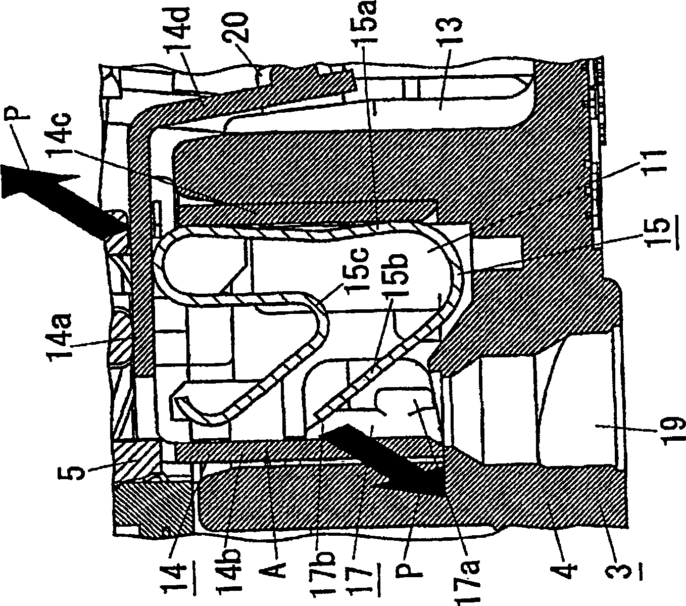
[0034] Next, a description will be given of a case where the terminal device of the present invention is applied to a switch. It is to be understood, however, that the application of the present invention is not limited to switches, and that the present invention is also applicable to wiring devices such as outlet sockets, and other appliances.

[0035] Such as figure 2 As shown, the switch 1 shown in this embodiment includes a housing 3 and a front surface provided on the housing 3 ( figure 2 The button handle 2 on the top surface in order to be depressed by the user. The switch 1 is a three-phase type switch in which the connection state of the contact device accommodated in the housing 3 is switched every time the button handle 2 is depressed. The following will refer to figure 2 , 3A and 3B describe the construction of switch 1 . In the following description, the words "top", "bottom", "left" and "right" are based on the Figure 3A The direction in which to look. ...


PUM


Abstract

A terminal device includes a terminal piece for making contact with a core wire of an electric wire inserted into a housing through a wire insertion hole formed in the housing; a locking spring formed separately from the terminal piece for mechanically and electrically connecting the core wire to the terminal piece by gripping the core wire in cooperation with the terminal piece; and a release button for releasing mechanical connection between the terminal piece and the core wire maintained by the locking spring, by being operated through a manipulation hole formed in the housing and the release button is provided with a pressure contact portion for, when the core wire is not inserted, pressing to bend the locking piece such that a gap is formed between the terminal piece and the leading edge of the locking piece.

Description

technical field [0001] The invention relates to a terminal device with a quick connection terminal structure capable of connecting electric wires without using screws. Background technique [0002] In general, there have been terminal devices known as quick-connect terminal structures capable of connecting electric wires without using screws, so that electric wires can be easily connected to wiring devices such as switches or outlet sockets (see, for example, Patent Literature 1). Next, the configuration of such a terminal device will be described. [0003] Figure 6A and 6B Shown are terminal arrangements A1 and A3 for use in a switch 1 comprising a housing 3, a push button handle 2 provided on the front of the housing 3, and a contact device B housed in the housing in such a manner. body 3 so that it reverses each time the button handle 3 is pressed. Each of the terminal devices A1 and A3 includes a terminal piece 14b or 18b electrically connected to the contact device...

Claims


Application Information

Patent Timeline
Patent Type & Authority Patents(China)
IPC IPC(8): H01R4/48
CPCH01H21/18H01R4/48
Inventor 草间公男
Owner MATSUSHITA ELECTRIC WORKS LTD