
Safety apparatus of passenger conveying equipment

A technology for passenger conveying equipment and safety devices, applied in the field of passenger conveying equipment, can solve problems such as cost increase, cost increase, collision sensor damage, etc., and achieve the effect of improving safety

Inactive Publication Date: 2009-09-30
HITACHI LTD
View PDF9 Cites 0 Cited by
  • Summary
  • Abstract
  • Description
  • Claims
  • Application Information

AI Technical Summary

Problems solved by technology

However, there is a risk that if the comb teeth are damaged due to collision with a foreign object, the collision sensor will also be damaged
In this case, the collision sensor has to be exchanged together with the exchange of the comb teeth of the passenger conveyor, resulting in an increase in cost
Moreover, the comb-like teeth arranged on the floor of the entrance and exit are generally provided in a plurality along the width direction of the floor of the entrance and exit, which also becomes a cause of increased cost.
On the other hand, in the safety device described in the above-mentioned Japanese Unexamined Patent Publication No. 7-101663, since it only relies on the noise meter to measure the abnormal presence or absence of noise, it is difficult to detect obstruction when a foreign object is blocked on the entrance / exit floor. The case of circular drives for passenger conveyors

Method used


Image

  • Safety apparatus of passenger conveying equipment
  • Safety apparatus of passenger conveying equipment
  • Safety apparatus of passenger conveying equipment

Examples


Embodiment Construction

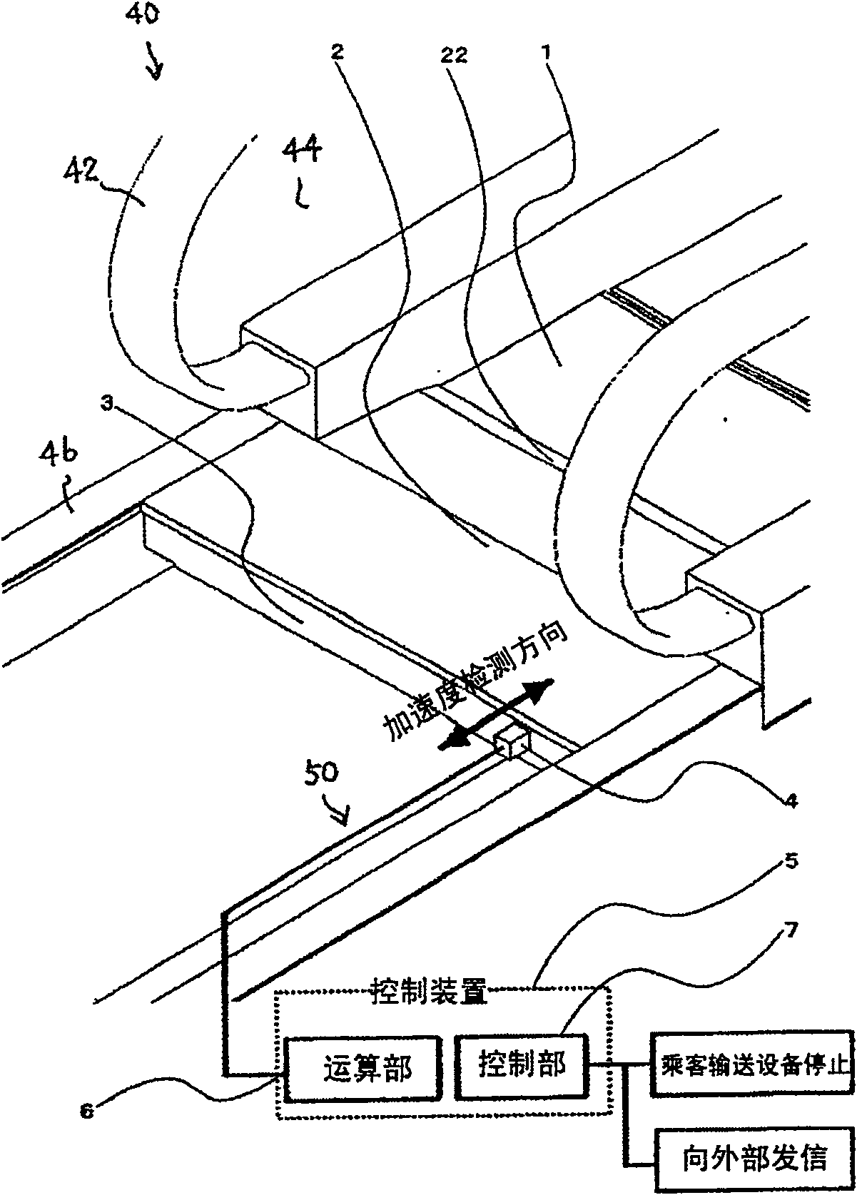
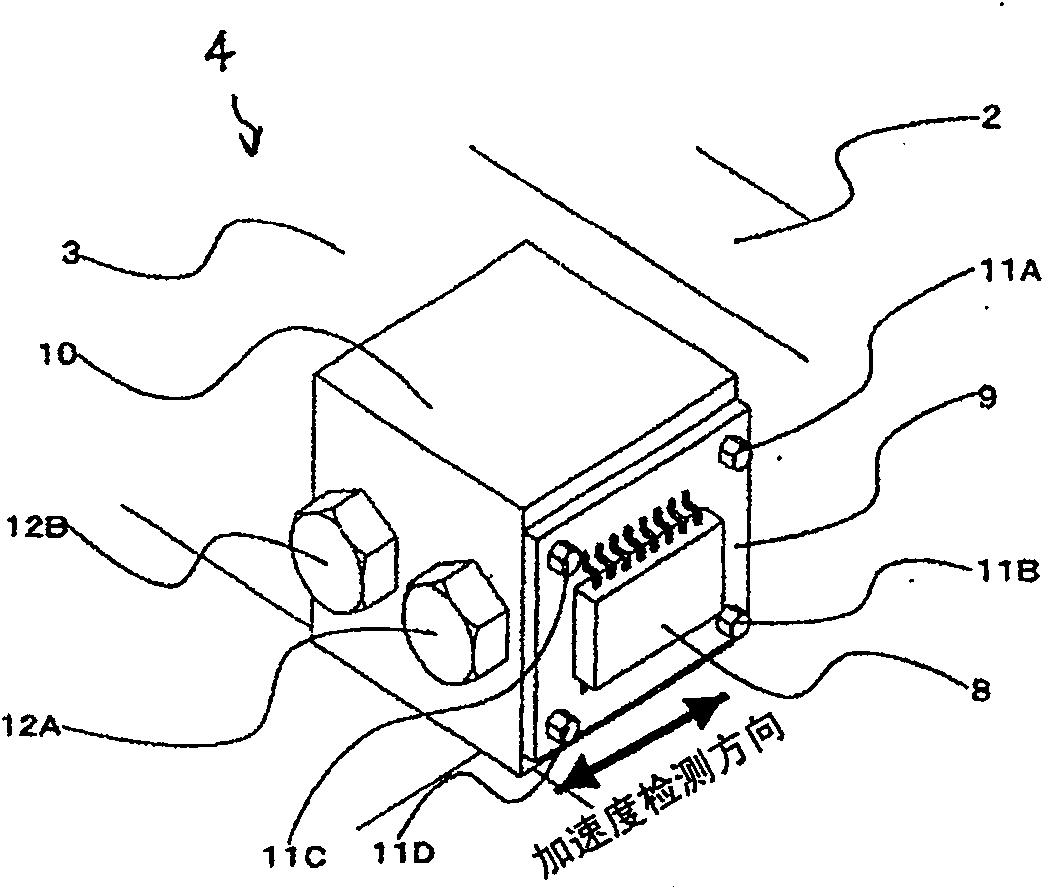
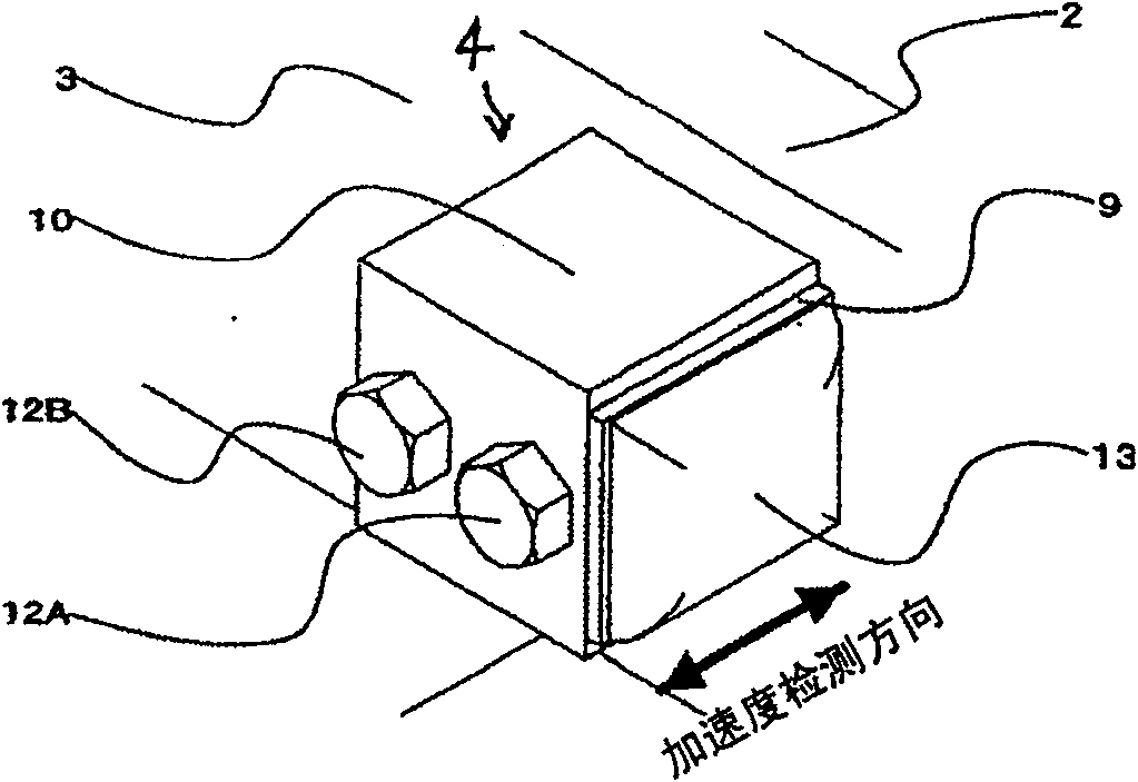
[0015] Next, an embodiment of the safety device of the passenger conveying facility according to the present invention will be described with reference to the drawings. figure 1 The lower end of the passenger conveyor 40 is shown in perspective. Below between railings 44 formed together with the left and right handrails 42, the steps 1 connected in a ring shape are arranged. A plurality of parallel grooves and protruding comb-shaped teeth 22 are formed on the upper surface and the arc surface on the front side of the pedal 1 . The entrance and exit floor 2 is arranged so as to be horizontally overlapped with a part of the footboard 1 . A plurality of parallel grooves and protruding comb-shaped teeth 22 are also formed on the upper surface of the access floor 2 . The entrance / exit floor 2 is stationary, and a main frame body 46 is arranged on the end in the width direction. An entrance and exit floor support beam 3 is also arranged, and the entrance and exit floor support be...


PUM


Abstract

A safety device for a passenger conveying facility has a tread that is formed in a ring shape and is cyclically driven, and an entrance / exit floor provided on an end portion of a ring of the ring tread and having a plurality of comb-shaped teeth thereon. An acceleration sensor unit is provided on a doorway floor or on a doorway floor support beam for supporting the doorway floor. Based on the acceleration signal detected by the acceleration sensor unit, the control device determines abnormality of the passenger conveying facility. If it is judged to be abnormal, the passenger conveyor is stopped or operated at a low speed.

Description

technical field [0001] The present invention relates to passenger conveying equipment, and in particular to safety devices therefor. Background technique [0002] An example of a conventional safety device for a passenger conveyor is disclosed in JP-A-5-155576. In this gazette, when a foreign matter clogs the entrance / exit floor portion of a passenger conveying facility, an abnormal situation due to the foreign matter clogging is avoided. Specifically, an impact sensor is provided on the comb-like portion formed at the front end of the entrance floor, and if a foreign object is clogged and a collision occurs, the impact sensor can detect the impact and report an abnormality. [0003] Another example of the safety device of the conventional passenger conveyance facility is described in Unexamined-Japanese-Patent No. 7-101663. In this gazette, a noise meter is installed near the entrance floor. And, the cycle of the sound obtained from the noise meter is the same cycle as t...

Claims


Application Information

Patent Timeline
Patent Type & Authority Patents(China)
IPC IPC(8): B66B29/02
Inventor 礒谷仁浜田朋之阿部义雄山下智典
Owner HITACHI LTD
Learn More