Supercharge Your Innovation With Domain-Expert AI Agents!

Cleaning mop

A mop and cleaning technology, which is applied in the field of mop with retractable handle, can solve the problems such as difficulty in putting on and taking off the cleaning tray and mop, uneven force, setting obstacles, etc.

Inactive Publication Date: 2009-12-02
脱普日用化学品(中国)有限公司
View PDF11 Cites 0 Cited by
  • Summary
  • Abstract
  • Description
  • Claims
  • Application Information

AI Technical Summary

Problems solved by technology

[0003] At present, mops with various shapes and performances have been developed. However, some mops are too bulky because the mop rod cannot be retracted, which not only takes up space when placed, but also cannot meet the needs of people of different heights.
In view of the aforementioned shortcomings, people have developed a mop with an adjustable handle length, but there are still problems that are difficult to solve, that is, the mop adjustment rod is easy to slide and shift when applying force, although people use various means to prevent the outer tube of the mop rod from moving vertically. Sliding with the inner rod tube, such as increasing the friction between the outer wall of the positioning member and the outer tube, setting obstacles, etc., but still cannot fundamentally solve the problem, which brings great inconvenience to people during use
[0004] In addition, currently known cleaning mops are generally attached to the cleaning tray with other materials specially used for bonding as auxiliary materials to connect the mop pad, or use the mop pad to cover the outside of the mop cleaning tray. There are often adhesive accessories that peel off and fail, and it is not easy to put on and take off between the cleaning tray and the mop. Excessive force is used to put on and take off, causing dust to be scattered, or the tightness of the wear and tear is not enough, and the force is uneven during the mopping process.
[0005] In addition, currently known cleaning mops generally use ordinary mops, and there are also mops made of microfiber knitting, but the loops or fibers of the mop are vertical to the surface of the fabric, and there is too much resistance to wet use during use, or some One side is too close to the surface to take advantage of the overall flat surface of the microfiber cleaning mop pad

Method used


Image

  • Cleaning mop
  • Cleaning mop
  • Cleaning mop

Examples


Embodiment 1

[0058] The structure of embodiment 1 mop

[0059] mop handle

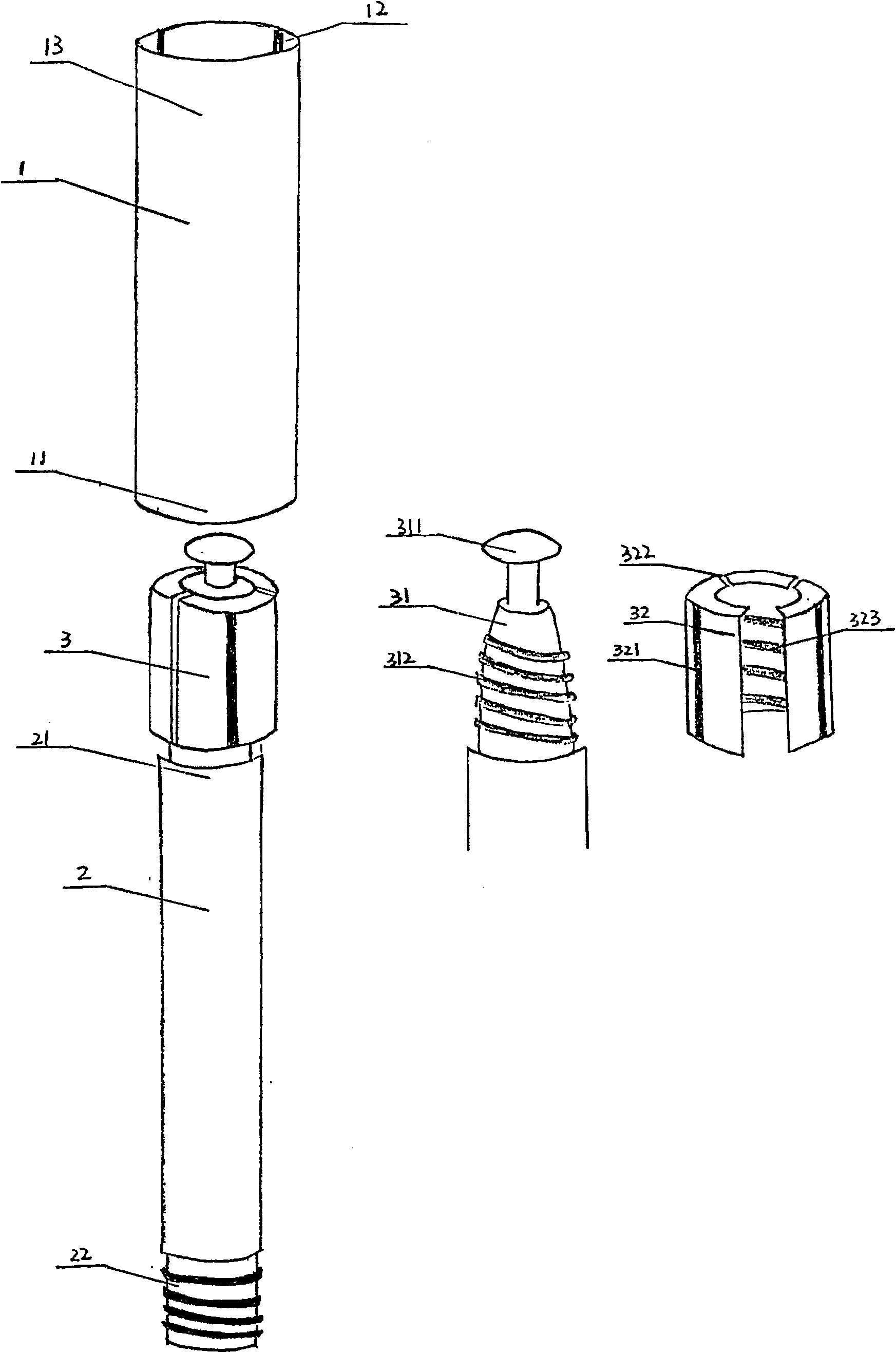
[0060] The mop handle of the present invention is as figure 1 As shown, the handle includes a main rod tube 1 and a secondary rod tube 2, the diameter of the secondary rod tube 2 is smaller than the main rod tube 1, and the upper tube end 21 of the secondary rod tube 2 is inserted into the lower tube of the main rod tube 1 within terminal 11;

[0061] The inner wall of the main rod tube 1 is provided with 2-9 ridges 12 with a thickness of 0.1-0.5 mm (more preferably, 0.1-0.4 mm) in parallel in the radial direction; the width of the ridges is 0.5 -4mm, preferably 1-2mm;

[0062] The upper pipe end 21 of the auxiliary rod pipe 2 is provided with a positioning member 3, and the positioning member 3 includes a screw shaft 31 fixed on the upper pipe end 21 of the auxiliary rod pipe 2, and a movably sleeved The radially non-closed elastic helical sleeve 32 on the helical shaft 31, the top of the helical shaft 31 form...

Embodiment 2

[0107] Embodiment 2 Telescopic adjustment of the mop handle

[0108] When using the mop of the present invention, first adjust the handle of the mop to a suitable length, specifically, including the steps of: inserting the upper tube end 21 of the secondary rod tube 2 into the lower tube end 11 of the main rod tube 1 , so that the sub-rod tube 2 moves in the main rod tube 1, and when it moves to an appropriate position, the sub-rod tube 2 is rotated, thereby driving the elastic helical sleeve 32 sleeved on the helical shaft 31 along the inner diameter of the helical shaft 31 The gradually increasing thread 312 rotates, and after rotating to a certain degree, the groove 322 on the elastic helical sleeve 32 fits with the convex strip 12 on the inner wall of the main rod tube 1, thereby preventing the elastic helical sleeve 32 from continuing rotate. The cross-sectional view of the main rod pipe 1 is as Figure 5 Shown in A; the cross-sectional view of the matching of the elast...

Embodiment 3

[0110] The stress test of embodiment 3 mop handle

[0111] Determination of the torque of the main rod tube and the secondary rod tube:

[0112] When the secondary rod tube is pulled to the top, tie the top of the main rod tube, and apply a torque at an appropriate point in the middle of the secondary rod tube without slipping. This torque is the torque of the main rod tube and the secondary rod tube.

[0113] Determination of the push-pull force after the telescopic rod is locked:

[0114] Fully stretch the main rod tube and the auxiliary rod tube, tighten them with a torque of 7kgf.cm, and push back the thrust at the top;

[0115] Fully compress the main rod tube and the sub rod tube, tighten it with 7kgf.cm torque, and pull it out at the top.

[0116] When the telescopic rod is retracted with a torque of 10kgf.cm, one end is tied to the handle, and the other end is tied to the lower end. The vertical force value is the axial tension of the telescopic rod.

[0117] testin...


PUM


Abstract

The invention belongs to the field of cleaning utensils and discloses a mop with an adjustable handle length. The secondary rod tube of the handle of the mop can be freely expanded and fixed in the main rod tube, and has double anti-slip effects in the horizontal and vertical directions when fixed. . More particularly, the mop of the present invention can be easily loaded and unloaded by using the mop directly injection-molded on the cleaning tray and using it in conjunction with the chemical fiber knitted Velcro fabric. More particularly, the inventor also added a layer of absorbing load-bearing layer between the hook and loop fabric and the mop, which can not only effectively keep the mop wet, but also make the mop evenly stressed during use. More particularly, the inventors also made a mop by knitting microfiber yarns and non-microfiber yarns in interlaced stripes into a terry towel tissue dumped to one side, so as to achieve one-way drag reduction and dirt storage. The mop of the invention has the advantages of simple structure, convenient use and ideal cleaning effect.

Description

technical field [0001] The invention belongs to the field of cleaning appliances, and relates to a mop, and more specifically, the invention relates to a mop with a retractable handle. Background technique [0002] With the improvement of people's material living standards, the requirements for various daily cleaning tools are also gradually increasing. People need cleaning tools that are simple in structure, easy to use, ideal in cleaning effect and easy to store. [0003] At present, mops with various shapes and different performances have been developed. However, some mops are too bulky because the mop rod cannot be retracted, which not only takes up space when placed, but also cannot meet the needs of people of different heights. In view of the aforementioned shortcomings, people have developed a mop with an adjustable handle length, but there are still problems that are difficult to solve, that is, the mop adjustment rod is easy to slide and shift when applying force, a...

Claims


Application Information

Patent Timeline
Patent Type & Authority Patents(China)
IPC IPC(8): A47L13/20B25G1/04
Inventor 洪进正
Owner 脱普日用化学品(中国)有限公司
Features
  • R&D
  • Intellectual Property
  • Life Sciences
  • Materials
  • Tech Scout
  • Unparalleled Data Quality
  • Higher Quality Content
  • 60% Fewer Hallucinations
Learn More