

Front-light back-light film set fixed structure
A fixed structure, backlight diaphragm technology, applied in optics, optical components, nonlinear optics, etc., can solve the problems of film displacement and deformation of multilayer optical diaphragms, optical diaphragm deformation, etc.
- Summary
- Abstract
- Description
- Claims
- Application Information
AI Technical Summary
Problems solved by technology
Method used
Image

Examples
no. 1 example
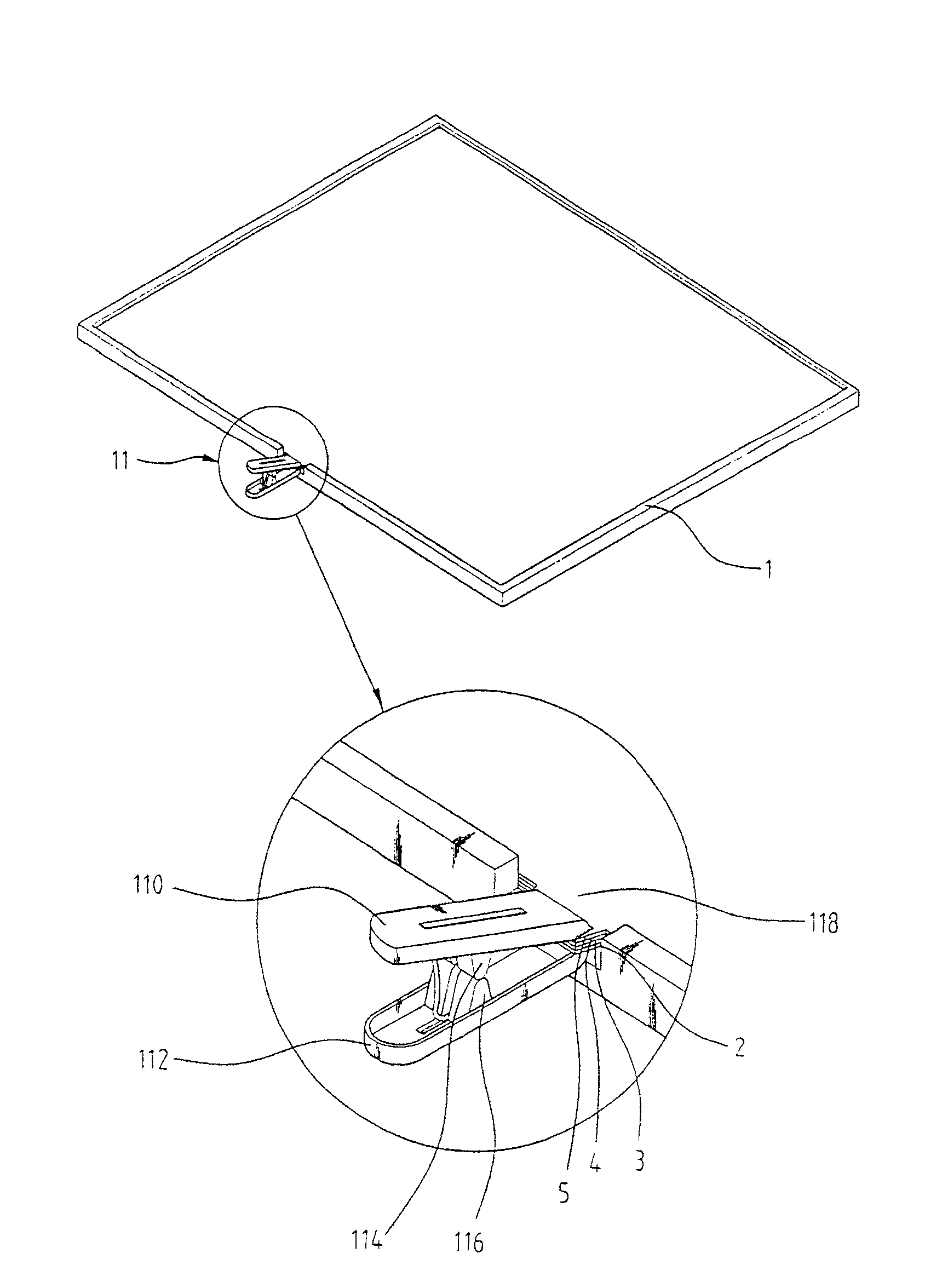
[0026] figure 1 According to the first embodiment of the present invention, the fixed structure diagram of the front light backlight diaphragm group mainly contains the parts mentioned below in this paper: a liquid crystal light valve (not shown in figure 1 ), an illumination mechanism 1, which is used to illuminate the liquid crystal light valve, and the illumination mechanism 1 itself has a planar light source (wave guide type plannar light source) of a waveguide type plate and a substrate (substrate) (not shown in figure 1 ), the substrate 10 itself is placed facing the light source, and has multi-layer optical films (multi-layer optical films) 2, 3, 4, 5 interposed between the substrate 10 and the light source, so that the selective reflection part is formed by the waveguide type The light emitted by the planar light source of the flat panel does not affect the color filter, so that the light emitted from the light source has a small divergence range, and the multilayer op...
no. 2 example
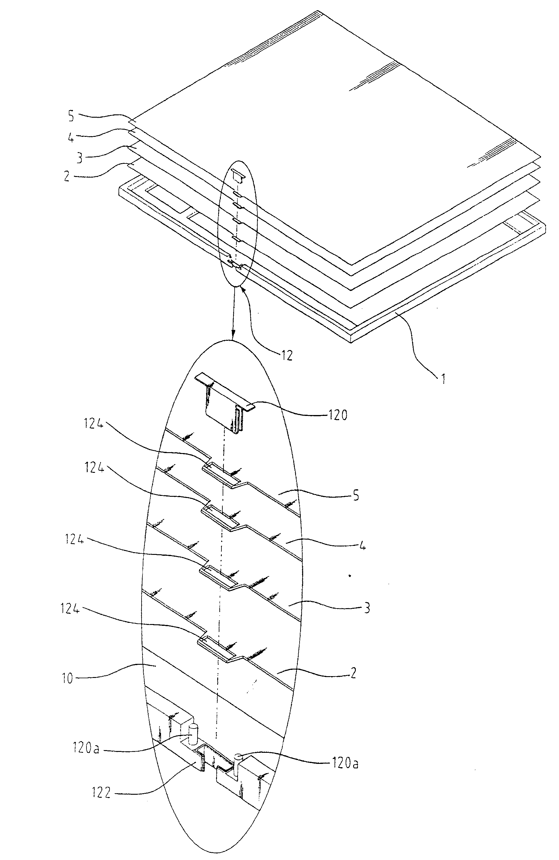
[0032] figure 2 For according to the second embodiment of the present invention, the front light and backlight diaphragm group fixed structure diagram mainly contains the parts mentioned below in this paper: a liquid crystal light valve (not shown in figure 2 ), an illumination mechanism 1, which is used to illuminate the liquid crystal light valve, and the illumination mechanism 1 itself has a planar light source (wave guide type plannar light source) of a waveguide type plate (not shown in figure 2 ) and a substrate (substrate) 10, the substrate 10 itself is placed facing the light source, and has multi-layer optical films (multi-layer optical films) 2, 3, 4, 5 interposed between the substrate 10 and the light source, so as to select Reflect part of the light emitted by the planar light source of the waveguide flat plate without affecting the color filter, so that the light emitted from the light source has a small divergence range, and the multilayer optical film 2, 3, 4...
no. 3 example
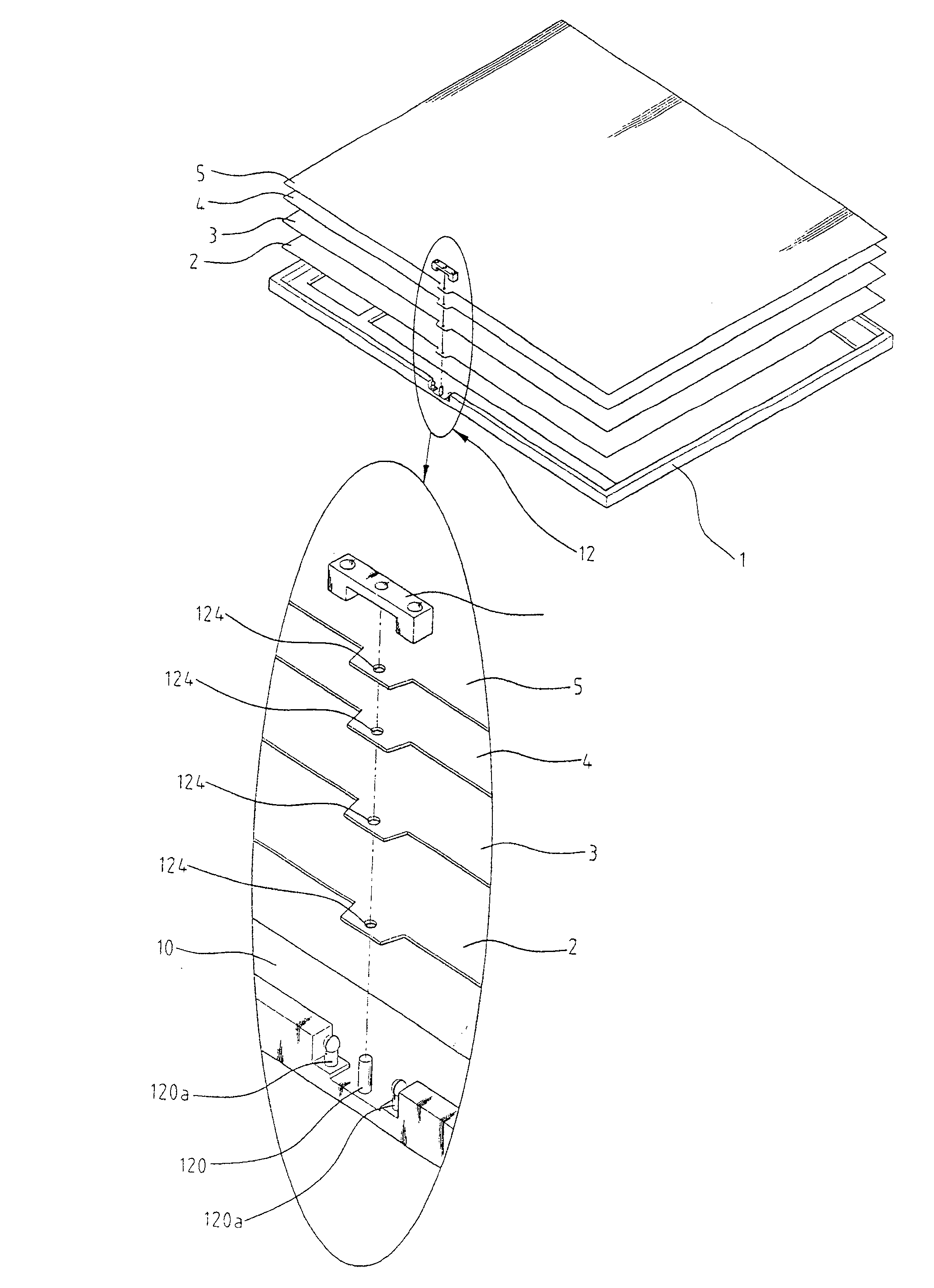
[0038] image 3 According to the third embodiment of the present invention, the fixed structure diagram of the front light backlight diaphragm group mainly contains the parts mentioned below in this paper: a liquid crystal light valve (not shown in image 3 ), a lighting mechanism 1, which is used to illuminate the liquid crystal light valve, and the lighting mechanism 1 itself has a wave guide type planar light source (wave guide type plannar light source) and a substrate (substrate) 10, the substrate 10 itself placed to face the light source, and have multi-layer optical films (multi-layer optical films) 2, 3, 4, 5 interposed between the substrate 10 and the light source, so as to selectively reflect part of the light emitted by the planar light source of the waveguide type plate light, and does not affect the color filter, so that the light emitted from the light source has a small divergence range, and multi-layer optical films (multi-layer optical films) 2, 3, 4, 5 can be...
PUM
 Abstract
Description
Claims
Application Information