Unlock instant, AI-driven research and patent intelligence for your innovation.

Video quality evaluation device and video quality evaluation method

A technology for image quality and evaluation devices, applied in image communication, television, electrical components, etc., can solve problems such as difficulty in obtaining reference image signals and deteriorating image signal position correspondence, timing deviation from timing, fluctuations, etc.

Active Publication Date: 2010-02-17
NIPPON TELEGRAPH & TELEPHONE CORP
View PDF6 Cites 0 Cited by
  • Summary
  • Abstract
  • Description
  • Claims
  • Application Information

AI Technical Summary

Problems solved by technology

In addition, there are times when information that is concentrated to some extent like data packets is lost
Therefore, it is difficult to obtain the spatial position correspondence between the reference video signal and the degraded video signal.
On the other hand, due to fluctuations in the arrival interval of IP packets or the occurrence of packet loss, phenomena such as deviations in timing of video display on the time axis or fluctuations in video display timing or freezing occur, which did not exist in the past.
Therefore, there is no way to achieve such a temporally offset match between the reference video signal and the degraded video signal
[0014] In the method of estimating the subjective quality of video, if the spatial and temporal position matching of the reference video signal and the degraded video signal cannot be sufficiently obtained, it will eventually be impossible to estimate the subjective quality of the video, and the accuracy will be low even if it is possible.

Method used


Image

  • Video quality evaluation device and video quality evaluation method
  • Video quality evaluation device and video quality evaluation method
  • Video quality evaluation device and video quality evaluation method

Examples


Embodiment Construction

[0075] Embodiments of the image quality evaluation device, image quality evaluation method, and image quality evaluation program, as well as the image matching device, image matching method, and image matching program of the present invention will be described in detail below with reference to the accompanying drawings. The first to third embodiments are embodiments of the invention of the video quality evaluation device, video quality evaluation method, and video quality evaluation program, and the fourth embodiment is an embodiment of the invention of the video matching device, video matching method, and video matching program.

[0076]

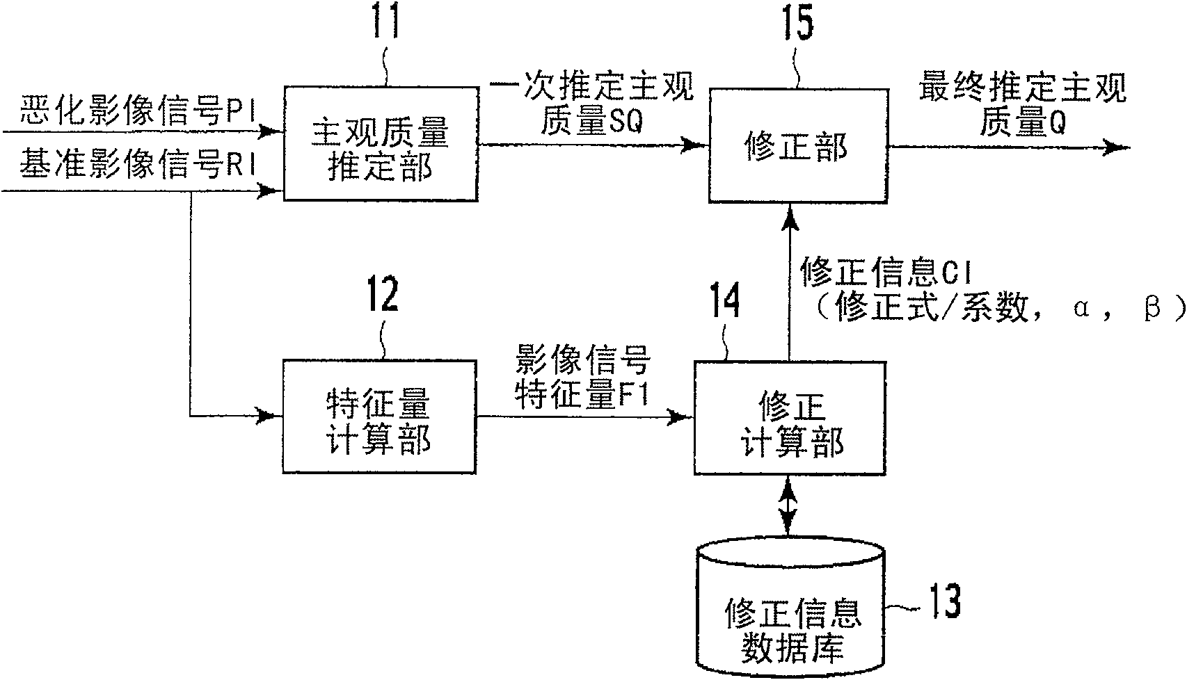
[0077] refer to figure 1 Each device part of the first embodiment of the video quality evaluation device of the present invention will be described. figure 1 It is a block diagram showing the configuration of the first embodiment of the video quality evaluation device of the present invention.

[0078] The video quality assessment device...


PUM


Abstract

A subjective quality estimation unit (11) receives a reference video signal (RI) as a video signal not deteriorated and a deteriorated video signal (PI) as the reference video signal deteriorated, calculates a video signal characteristic amount of the both signals, and estimates the subjective quality of the deteriorated video signal according to the difference between the video signal characteristic amounts of the both signals calculated. A characteristic amount calculation unit (12) calculates a video signal characteristic amount of the reference video signal. A correction information storage unit (13) contains correction information for correcting the subjective quality in accordance with the video signal characteristic amount. A correction calculation unit (14) acquires correction information corresponding to the video signal characteristic amount of the reference video signal received from the characteristic amount calculation unit (12), from a correction information storage unit(13) and passes it to a correction unit (15). According to the correction information received, the correction unit (15) corrects the subjective quality of the deteriorated video signal estimated by the subjective quality estimation unit (11).

Description

technical field [0001] The present invention relates to a video quality evaluation device, a video quality evaluation method, and a video quality evaluation that estimate subjective quality from measurement of physical feature quantities of video signals instead of a subjective quality evaluation test in which people view actual video. program. [0002] In addition, the present invention also relates to the determination of spatial and temporal positions between a reference video signal and a degraded video signal whose quality has deteriorated through encoding or network transmission in the video quality evaluation device, video quality evaluation method, and video quality evaluation program. The matching image matching device, image matching method and image matching program. Background technique [0003] Generally, the quality of image information will deteriorate through certain processing, such as encoding or network transmission. Regarding such a deteriorated video, ...

Claims


Application Information

Patent Timeline
Patent Type & Authority Patents(China)
IPC IPC(8): H04N17/04
Inventor 冈本淳栗田孝昭
Owner NIPPON TELEGRAPH & TELEPHONE CORP