

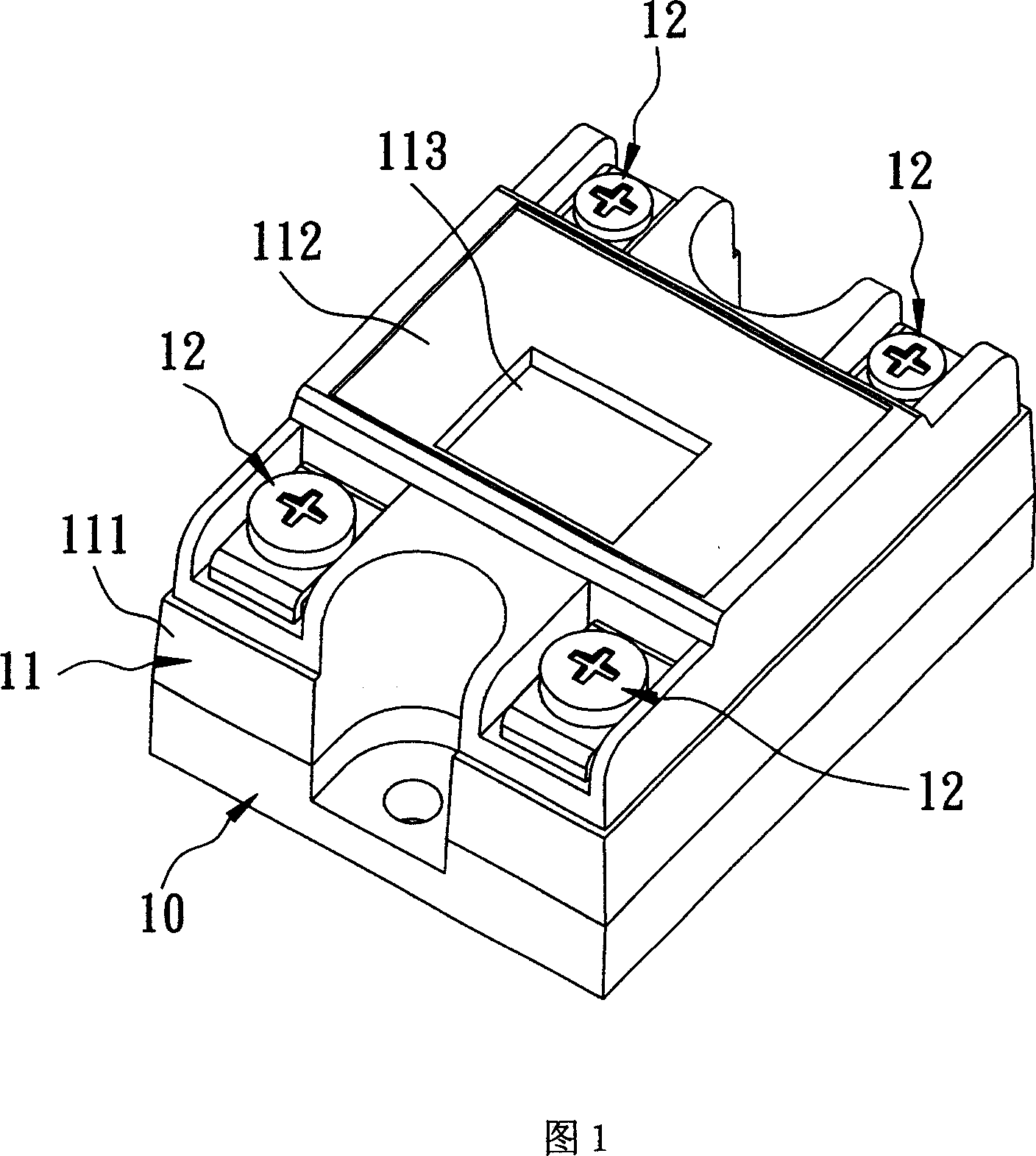
Relay with protection cover
A protective cover and relay technology, applied in the direction of relay ventilation/cooling/heating, relay base/shell/cover, etc., can solve the problems of inconvenient observation of filling degree, easy shaking of the shell 11, overflow of sealing glue, etc.
- Summary
- Abstract
- Description
- Claims
- Application Information
AI Technical Summary
Problems solved by technology
Method used
Image

Examples
Embodiment Construction
[0025] The present invention will be described in detail below in conjunction with the accompanying drawings and embodiments.
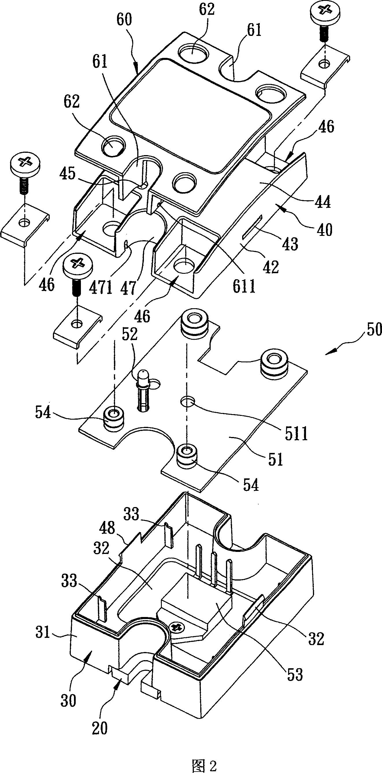
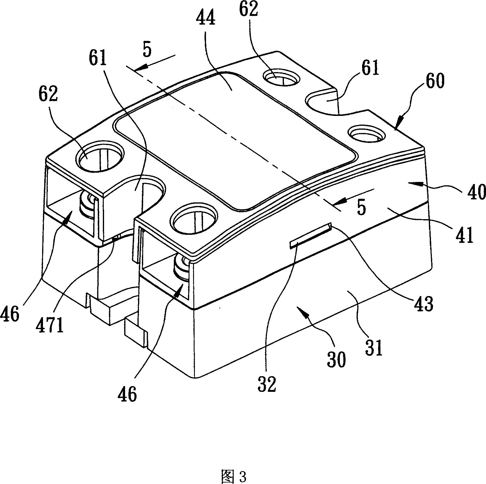
[0026] As shown in FIGS. 2 , 3 , and 4 , a preferred embodiment of the relay with a protective cover of the present invention includes a bottom plate 20 , a housing 30 , a shell 40 , a control unit 50 , and a protective cover 60 .
[0027] As shown in FIGS. 2 , 3 and 5 , the bottom plate 20 is a heat dissipation plate and includes a bottom wall 21 and a connecting wall 22 .
[0028] The bottom wall 21 has a first plate surface 211 , a second plate surface 212 opposite to the first plate surface 211 , and a surrounding surface 213 connected to the first and second plate surfaces 211 , 212 .
[0029] The connecting wall 22 protrudes from the surrounding surface 213 and has a concave portion 221 extending to the surrounding surface 213 and being concave relative to the second plate surface 212 .
[0030] The casing 30 is directly embedded in the periphe...
PUM
 Abstract
Description
Claims
Application Information