Method for detecting 3D defects on surface of belt material

A technology of strip surface and detection method, applied in the direction of measuring device, material analysis, material analysis by optical means, etc., can solve the problems of inability to obtain the contour shape of defects, inability to detect defects, and too late to deal with them, so as to shorten the initial inspection. The effect of time, imaging speed, and imaging space is small

Active Publication Date: 2007-07-25
BAOSHAN IRON & STEEL CO LTD
View PDF0 Cites 30 Cited by
  • Summary
  • Abstract
  • Description
  • Claims
  • Application Information

AI Technical Summary

Problems solved by technology

This method has two major disadvantages: First, the image collected by one imaging is only a line, which can only reflect the depth information of the defect at the position of the light, and cannot obtain the specific contour shape of the defect
Second, when the detection object moves at a high speed, it will be too late to deal with it, resulting in missed detection
Because the area array image sensor images a plane at a time, if the defect is just within the irradiation range of the laser beam, the defect can be detected correctly, otherwise the defect cannot be detected

Method used


Image

  • Method for detecting 3D defects on surface of belt material
  • Method for detecting 3D defects on surface of belt material
  • Method for detecting 3D defects on surface of belt material

Examples


Embodiment Construction

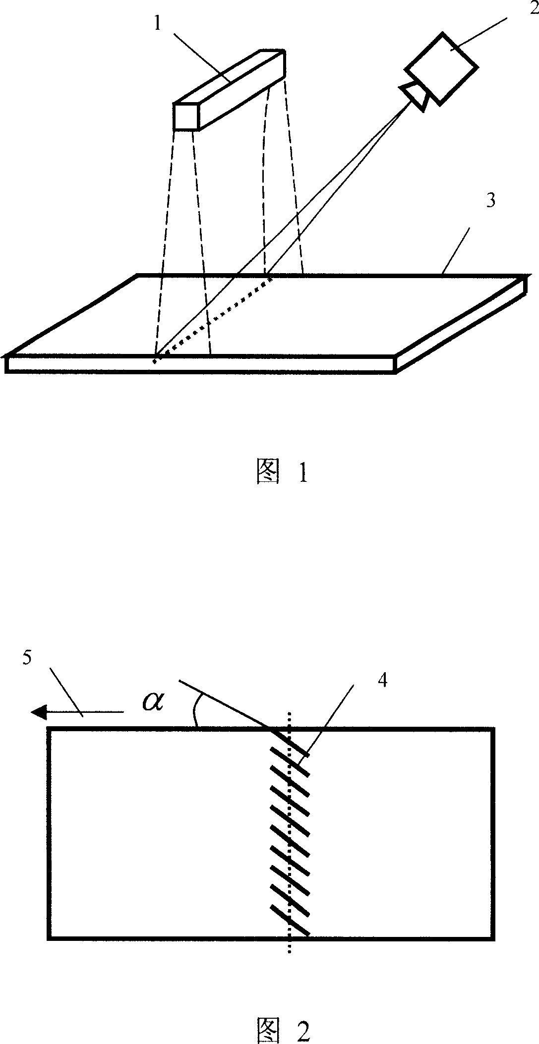
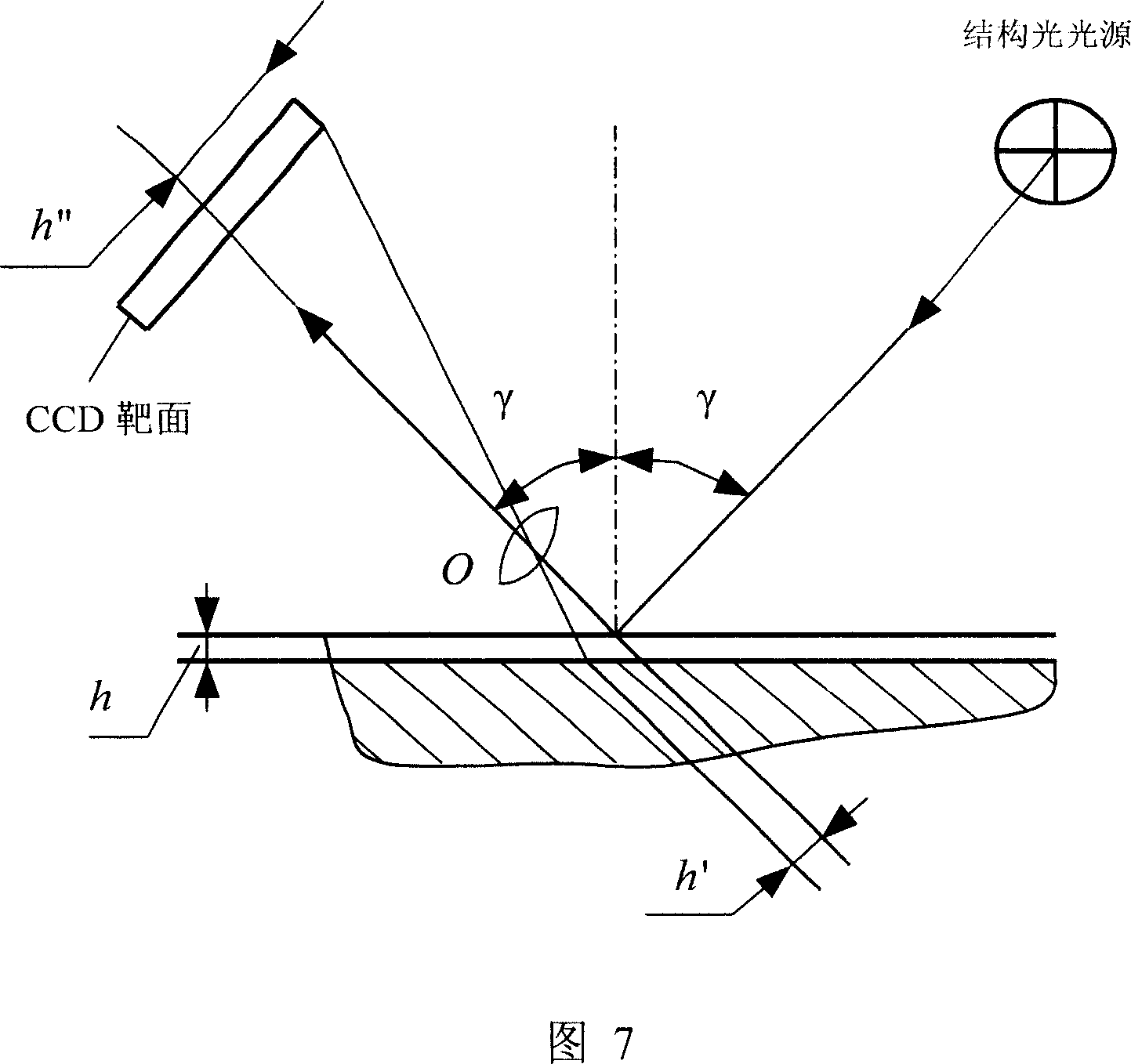
[0020] Referring to Fig. 1 and Fig. 2, a method for detecting three-dimensional defects on the surface of a steel strip is to use a structured light source 1 to project an array of light strips 4 of parallel short oblique lines from the front of the strip 3 to the surface of the moving strip 3, and the reflected light is captured The line-scanning CCD camera 2 placed above the steel strip 3 receives it, conducts preliminary judgment on the collected images, and classifies the defects according to the shape changes of the lines on the images. The light strips 4 of the array of parallel short oblique lines are projected onto the steel strip surface as shown in FIG. 2 . α (0°<α<90°) is the angle between the strip steel movement direction 5 and the light array 4 direction, and the α angle ensures that the strip steel 3 can be accurately detected when the line scan CCD camera 2 (line scan image sensor) is used. Surface three-dimensional defects.

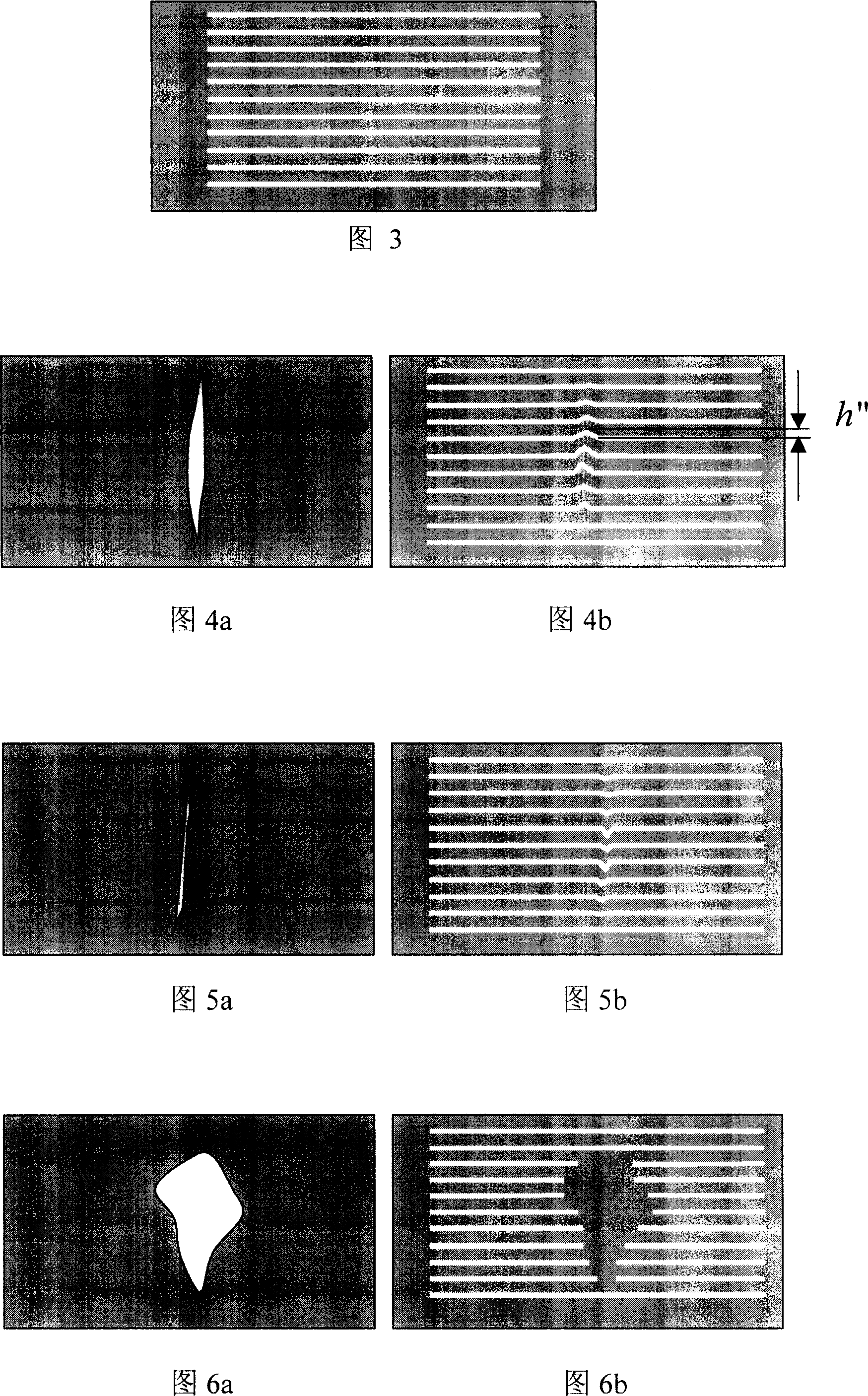
[0021] Referring to Fig. 3, if th...


PUM


Abstract

A method for detecting 3-D defect on surface of strip material includes projecting parallel short-tilted line array light belt onto surface of mobile strip material to be detected, receiving reflection light by linear scan video camera set above said strip material, carrying out preliminary judgment on collected image and classifying defects according to lien form variation on image, converting image with defects to be digital signal being inputted into computer then calculating out relative height of each point to finalize treatment on image.

Description

(1) Technical field [0001] The invention relates to a method for detecting three-dimensional defects on the surface of a strip, in particular to a method for detecting three-dimensional defects on the surface of a strip based on the combination of a structured light method and a line scanning image sensor. (2) Background technology [0002] At present, continuous production of strip materials, such as strip steel, strip aluminum, copper foil, paper, plastic and other materials, requires online detection of surface defects. At present, the most popular and successful inspection system is the solution using machine vision inspection technology, that is, using a high-speed camera to take images of materials on the production line, and using a computer to analyze whether there are defects and what kind of defects exist. This method has been widely used in major iron and steel enterprises in the world. In the surface three-dimensional defect detection system, the lighting mostly...

Claims


Application Information

Patent Timeline
Patent Type & Authority Applications(China)
IPC IPC(8): G01N21/892
Inventor 何永辉石桂芬
Owner BAOSHAN IRON & STEEL CO LTD
Why Eureka
Try Eureka