Reduction gear mounted on revolute joint part of industrial robot

An industrial robot and joint connection technology, which is applied in the direction of manipulators, manufacturing tools, mechanical equipment, etc., can solve the problem of the angle selection of the heat release of the front-stage spur gear, etc.

Inactive Publication Date: 2007-07-25
NABLESCO CORP
View PDF2 Cites 24 Cited by
  • Summary
  • Abstract
  • Description
  • Claims
  • Application Information

AI Technical Summary

Problems solved by technology

Therefore, the reduction ratio of the front-stage spur gear is not selected in consideration of heat release

Method used


Image

  • Reduction gear mounted on revolute joint part of industrial robot
  • Reduction gear mounted on revolute joint part of industrial robot
  • Reduction gear mounted on revolute joint part of industrial robot

Examples


Embodiment Construction

[0028] Embodiments of the present invention will be described below with reference to the accompanying drawings.

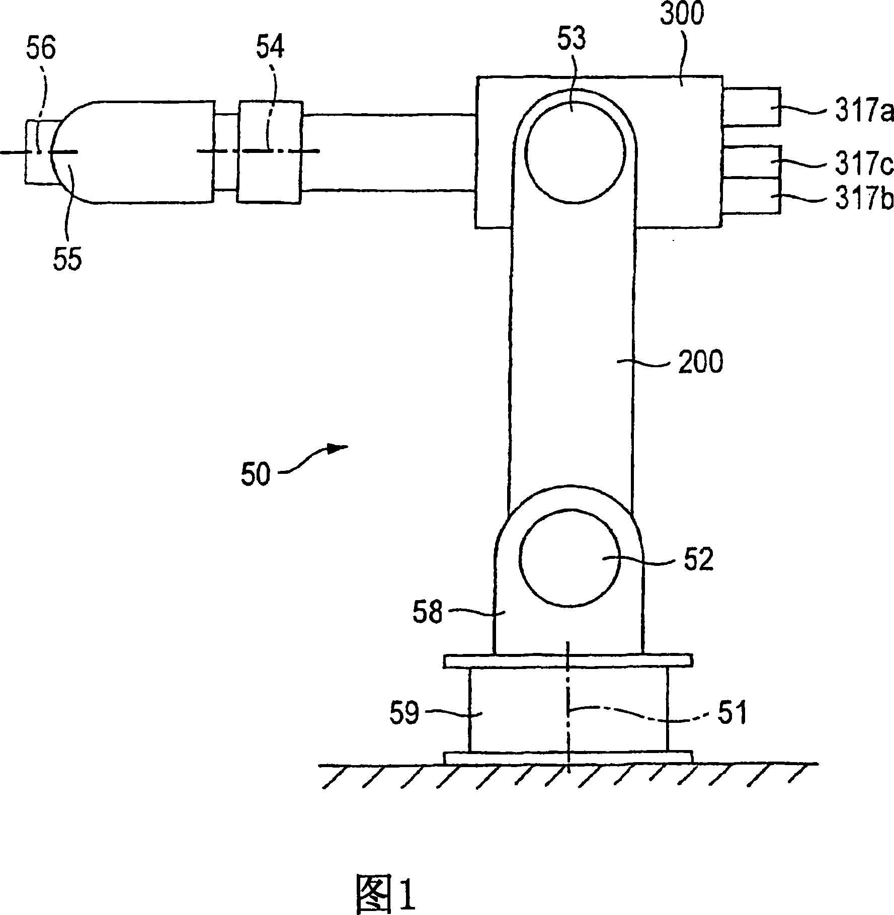
[0029] FIG. 1 is an overall view of an industrial robot 50 . The industrial robot 50 includes a J1-axis articulation part 51, a J2-axis articulation part 52, a J3-axis articulation part 53, a J4-axis articulation part 54, a J5-axis articulation part 55 and a J6-axis articulation part 56. A reducer is attached. There is a base end arm 58 (or swivel head) attached to the base 59 such that the base end arm 58 can rotate on the J1 axis articulation portion 51 . A first arm 200 described later is attached to the base end arm 58 so that the first arm 200 can rotate on the J2-axis articulation portion 52 .

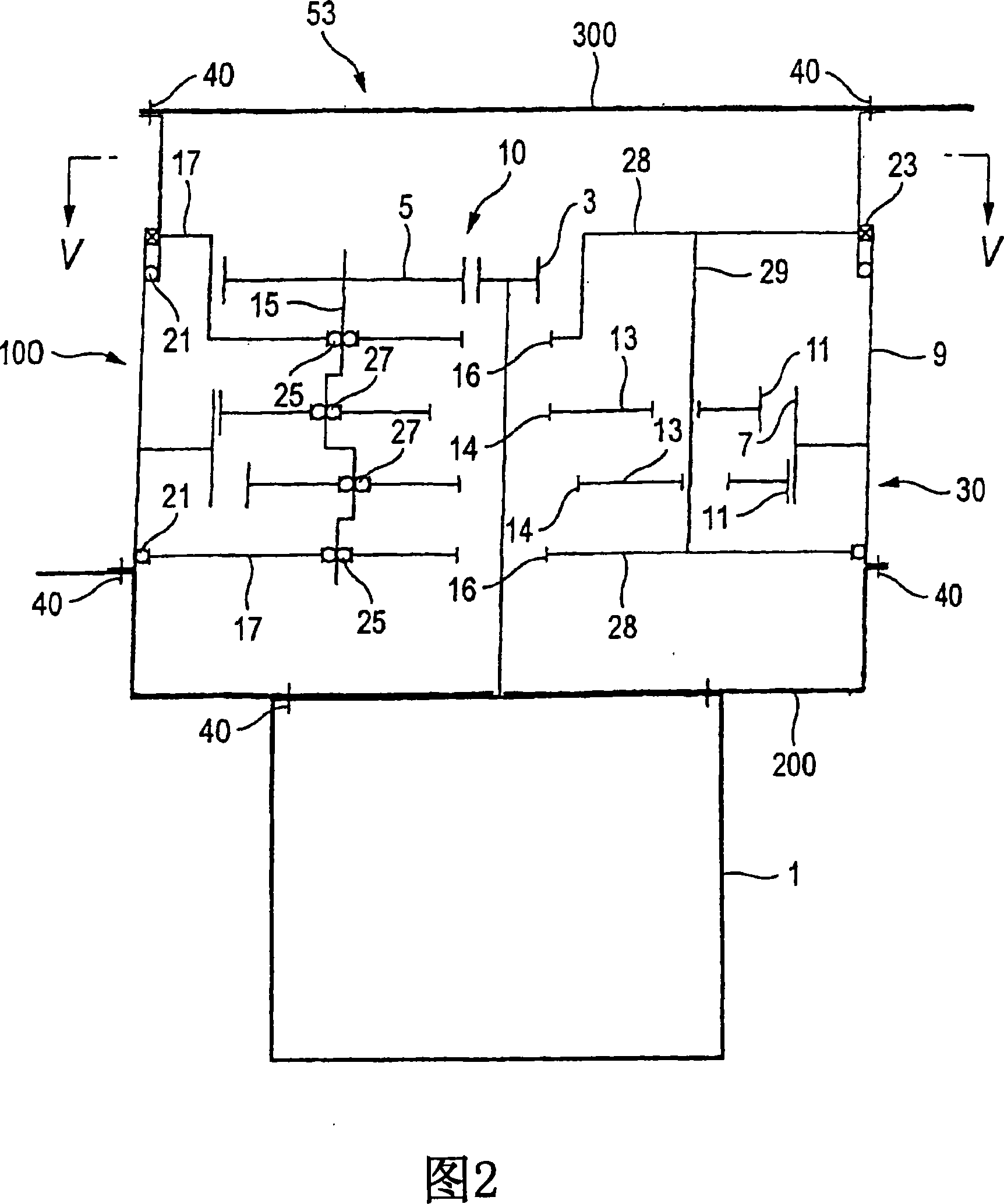
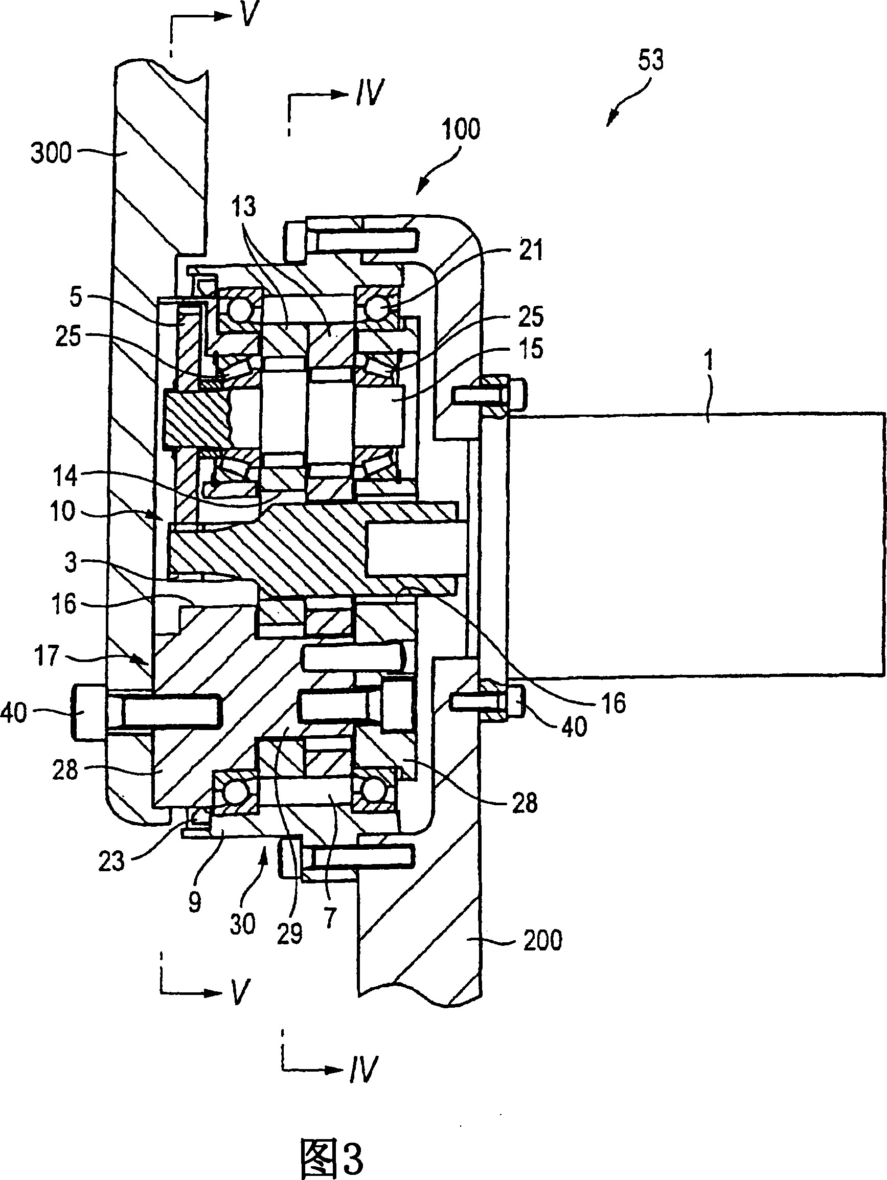
[0030] 2 is a schematic diagram showing a sectional structure of a speed reducer attached to a J3-axis articulation portion of an industrial robot according to a first embodiment of the present invention. FIG. 3 is a view showing the view shown in FIG. 2 with a sp...


PUM


Abstract

A speed reducer (100) installed at the articulation of an industrial robot, wherein a first stage speed reduction mechanism (10) comprises a spur gear speed reduction part and a second stage speed reduction mechanism (30) comprises an eccentrically oscillating speed reduction part. An output from the eccentrically oscillating speed reduction part is taken out from an internal gear body or a support body. When a rotational speed inputted into a first input gear part is 2000 rpm or higher, the speed reducer installed at the articulation of the industrial robot is rotated with an output from the eccentrically oscillating speed reduction part of20 rpm or higher. The reduction ratio of the first stage speed reduction mechanism is selected so that, when the speed reducer is rotated with the output from the eccentrically oscillating speed reduction part of 20 rpm or higher, crankshafts are not rotated at speeds beyond 1000 rpm.

Description

technical field [0001] The present invention relates to a speed reducer with reduced heat release and attached to an articulation part of an industrial robot. Background technique [0002] In the prior art, as a speed reducer for robot joint drive, there is known a two-stage speed reducer having spur gears at the front-stage unit of the eccentric swing type speed reducer. Such a speed reducer has the effect of avoiding the robot resonance phenomenon in a precision operation area such as welding operation by appropriately selecting the reduction ratio of the preceding unit with respect to the natural frequency and motor speed of the robot articulation drive system. Therefore, the speed reduction ratio in the preceding unit of the speed reducer is selected based on the relationship with the natural frequency, the motor speed, and the required overall speed reduction ratio (for example, refer to Patent Document 1). On the other hand, the output speed of the prior art reducer i...

Claims


Application Information

Patent Timeline
Patent Type & Authority Applications(China)
IPC IPC(8): F16H1/32B25J19/00
CPCY10T74/18056B25J9/102F16H1/32F16H2001/323B25J19/00
Inventor 栗田昌兆日比野敏晴广濑淳
Owner NABLESCO CORP
Why Eureka
Try Eureka