Processes for production of synthetic naphtha

A manufacturing method and a technology for naphtha, which are used in the catalytic reforming of naphtha, the preparation of liquid hydrocarbon mixtures, the petroleum industry, etc. Heat and unstable operation stabilization effect

Inactive Publication Date: 2013-01-30
JAPAN OIL GAS & METALS NAT CORP +5
View PDF4 Cites 0 Cited by
  • Summary
  • Abstract
  • Description
  • Claims
  • Application Information

AI Technical Summary

Problems solved by technology

In this way, due to the excessive heat release, changes in the process flow rate and olefin content directly lead to changes in the heat release, which easily makes the operation of the hydrotreating unit unstable.

Method used


Image

  • Processes for production of synthetic naphtha
  • Processes for production of synthetic naphtha
  • Processes for production of synthetic naphtha

Examples


Embodiment 1

[0086] (hydrofinishing of naphtha fractions)

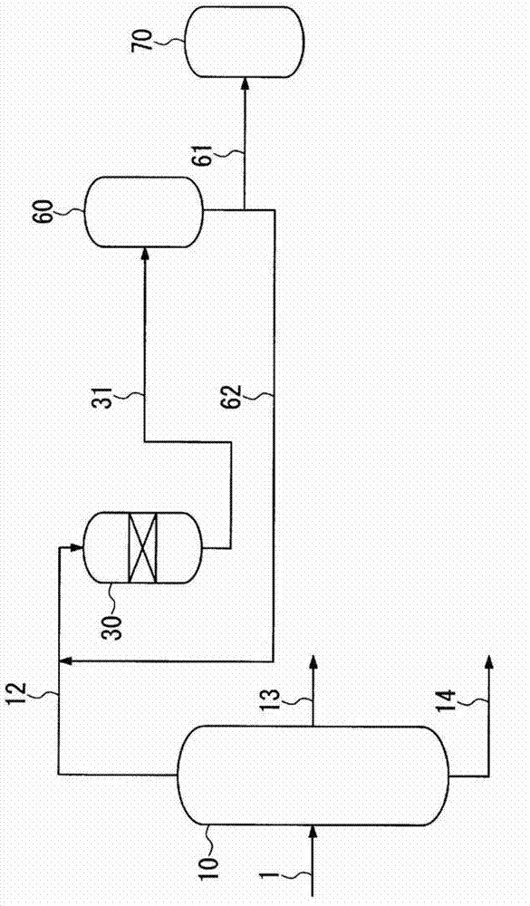
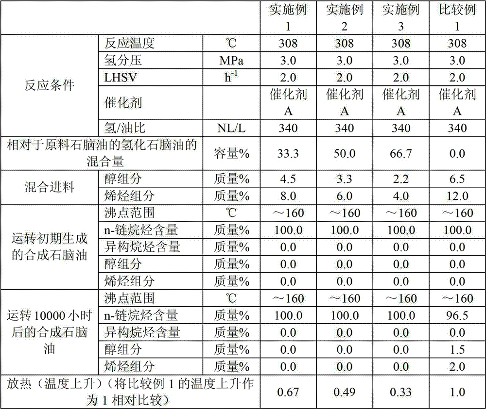
[0087] Fill hydrogenation catalyst A (150ml) in figure 1 In the flow-through reactor of the fixed bed, that is, the hydrotreating unit 30, the naphtha fraction (raw naphtha) obtained as above is supplied from the top of the reactor 30 at a rate of 300ml / h, Hydrotreating was carried out under the above reaction conditions.

[0088] That is to say, relative to the naphtha fraction, hydrogen is supplied from the top of the tower at a hydrogen / oil ratio of 340NL / L, and the back pressure valve is adjusted to stabilize the pressure of the reaction tower at an inlet pressure of 3.0MPa (hydrogen partial pressure) for hydrogenation. refined. The reaction temperature at this time was 308°C.

[0089] The naphtha fraction hydrotreated in the hydrotreating unit 30 is stored in a storage tank 70 from a line 61 via a stabilization column 60 from a line 31 .

[0090] Here, a part of the obtained hydrogenated naphtha fraction is recycled from ...

Embodiment 2

[0094] (hydrofinishing of naphtha fractions)

[0095] Catalyst A (150ml) is filled in a flow-through reactor of a fixed bed, that is, a hydrotreating unit 30, and the naphtha fraction (raw naphtha ), under hydrogen flow, under the following reaction conditions for hydrogenation treatment.

[0096] That is to say, relative to the naphtha fraction, hydrogen is supplied from the top of the tower at a hydrogen / oil ratio of 340NL / L, and the back pressure valve is adjusted to stabilize the pressure of the reaction tower at an inlet pressure of 3.0MPa (hydrogen partial pressure) for hydrogenation. refined. The reaction temperature at this time was 308°C.

[0097] Here, the obtained hydrogenated naphtha fraction was mixed with 50.0% by volume relative to the raw material naphtha, and after obtaining the mixed feed having the properties shown in Table 2, it was carried out under the same conditions as the above-mentioned hydrotreating conditions. Processing to obtain synthetic napht...

Embodiment 3

[0100] (hydrofinishing of naphtha fractions)

[0101] Catalyst A (150ml) is filled in a flow-through reactor of a fixed bed, that is, a hydrotreating unit 30, and the naphtha fraction (raw naphtha ), under hydrogen flow, under the following reaction conditions for hydrogenation treatment.

[0102] That is to say, relative to the naphtha fraction, hydrogen is supplied from the top of the tower at a hydrogen / oil ratio of 340NL / L, and the back pressure valve is adjusted to stabilize the pressure of the reaction tower at an inlet pressure of 3.0MPa (hydrogen partial pressure) for hydrogenation. refined. The reaction temperature at this time was 308°C.

[0103] Here, the obtained hydrogenated naphtha fraction was mixed at 66.7% by volume with respect to the raw naphtha, and after obtaining the mixed feed having the properties shown in Table 2, it was carried out under the same conditions as the above-mentioned hydrotreating conditions. Processing to obtain synthetic naphtha. Ta...


PUM

PropertyMeasurementUnit
boiling pointaaaaaaaaaa

Abstract

The present invention aims at providing a method of manufacturing naphtha, wherein, in hydrogenation of a naphtha fraction which is fractionated from synthetic oil (FT synthetic oil) obtained by Fisher-Tropsch synthesis, the hydrogenised component is recycled and the recycled amount thereof is adjusted to reduce a olefin content in a hydro-refining apparatus whereby heat generation is suppressed and unstable operation of the hydro-refining apparatus can be stabilized. Furthermore, the present invention relates to a method of manufacturing naphtha, wherein a cut point for fractionating a naphtha fraction from FT synthetic oil is adjusted to reduce the amount of olefin in a hydro-refining apparatus whereby unstable operation of the hydro-refining apparatus can be stabilized.

Description

[0001] This application is a divisional application of Chinese patent application No. 200880108565.4 (international application number PCT / JP2008 / 067308) submitted on March 24, 2010. technical field [0002] The present invention relates to a process for the manufacture of synthetic naphtha from synthetic oil obtained by the Fischer-Tropsch synthesis. Background technique [0003] In recent years, from the viewpoint of reducing the environmental load, there has been a demand for an environmentally friendly green liquid fuel with a low content of sulfur components and aromatic hydrocarbons. Therefore, in the petroleum industry, Fischer-Tropsch synthesis (hereinafter referred to as "FT synthesis") using carbon monoxide and hydrogen as raw materials has been studied as a method for producing green fuels. According to the FT synthesis method, since it is possible to produce a liquid fuel base material, such as a diesel fuel base material, which is rich in paraffins and does not ...

Claims


Application Information

Patent Timeline
Patent Type & Authority Applications(China)
IPC IPC(8): C10G67/02
CPCC10G2300/4081C10G2400/02C10G2/30C10G2300/1022C10G45/02C10G35/04
Inventor 田中祐一
Owner JAPAN OIL GAS & METALS NAT CORP
Why Eureka
Try Eureka