Cleanable press machine

A punching device and cleaning technology, applied in the field of punching device, to achieve the effect of simplifying the cleaning process

Inactive Publication Date: 2007-08-01
PTM PACKAGING TOOLS MACHINERY PTE
View PDF4 Cites 5 Cited by
  • Summary
  • Abstract
  • Description
  • Claims
  • Application Information

AI Technical Summary

Problems solved by technology

For the device this task is solved as follows: the punch is provided with a guide element for guiding the punch after it has been released from the seat sleeve

Method used


Image

  • Cleanable press machine
  • Cleanable press machine
  • Cleanable press machine

Examples


Embodiment Construction

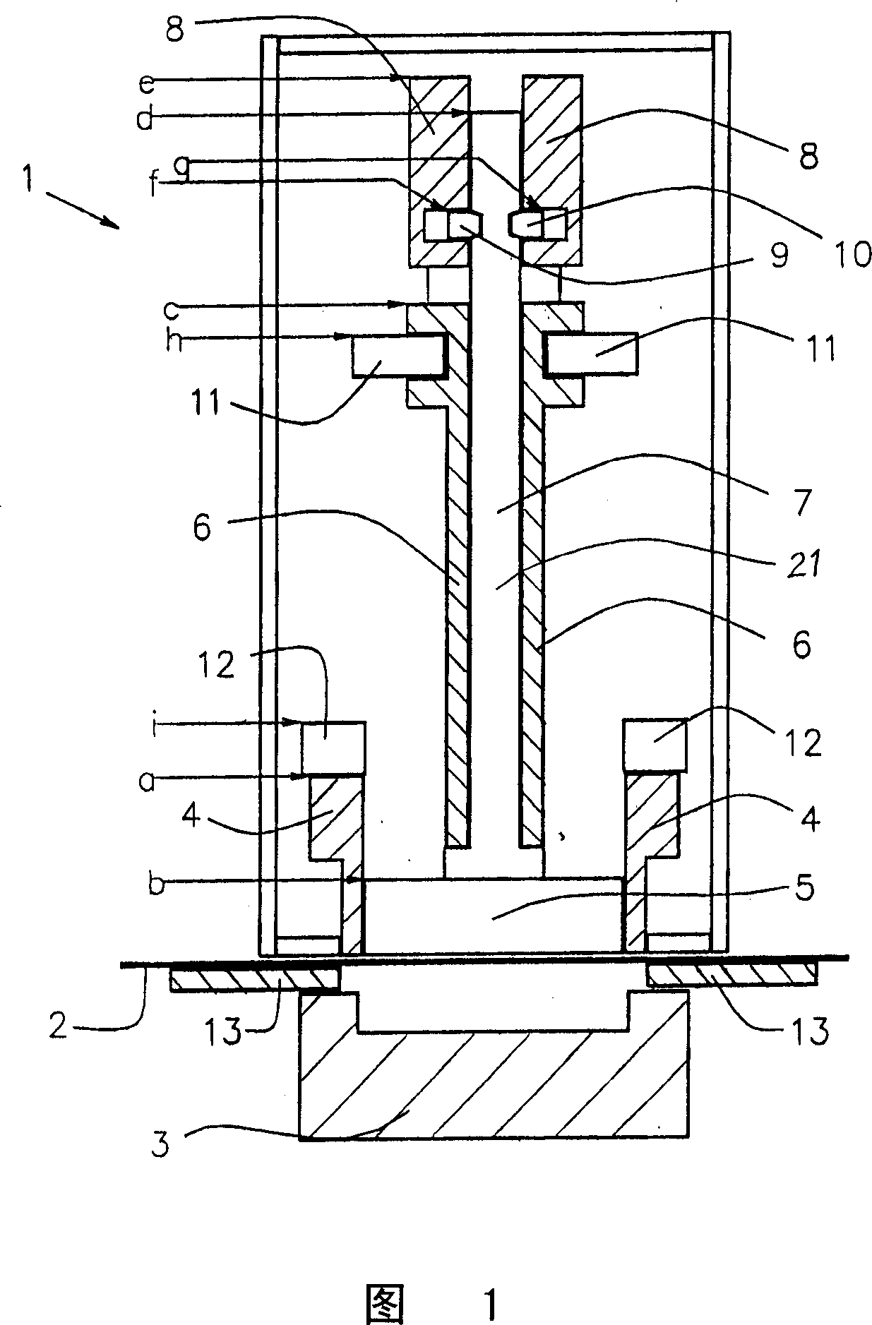
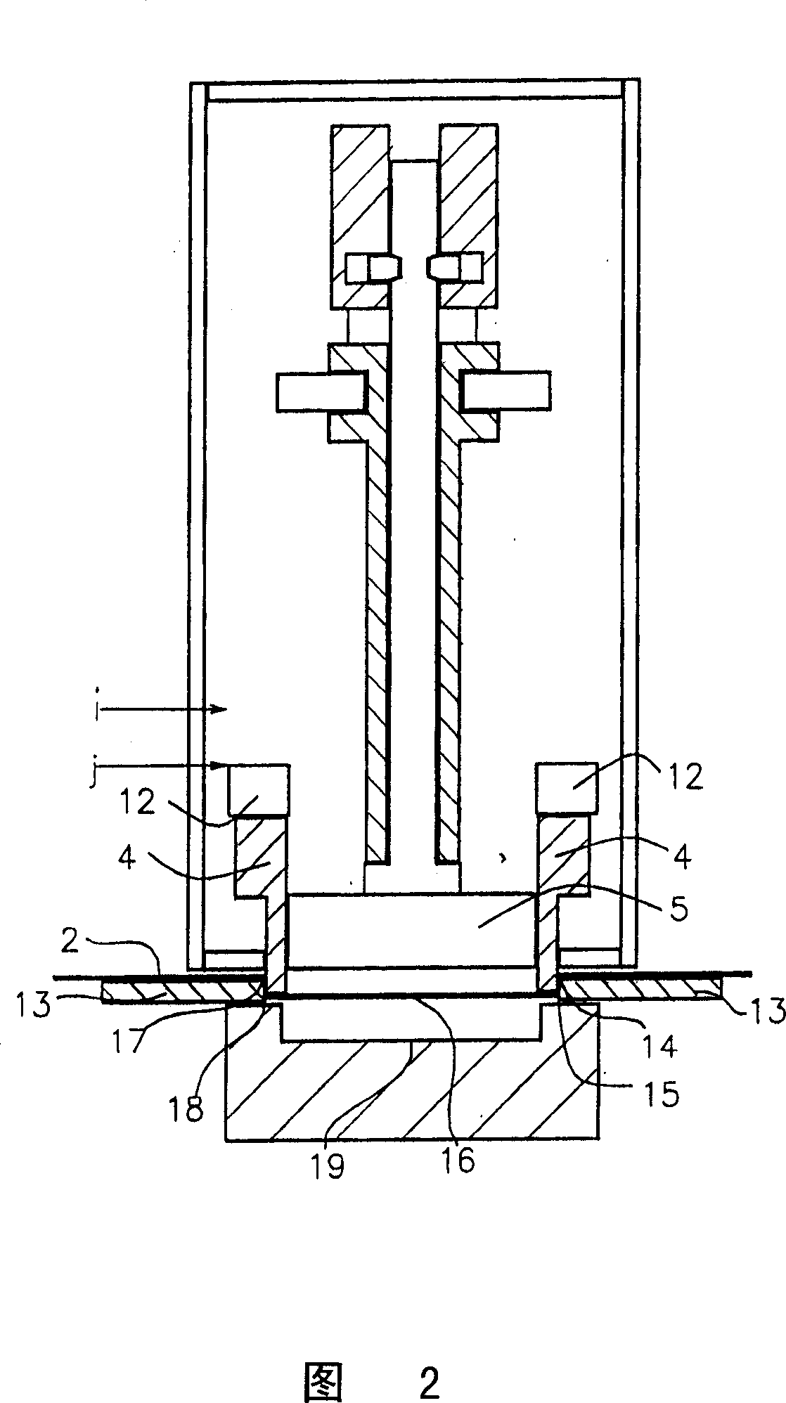
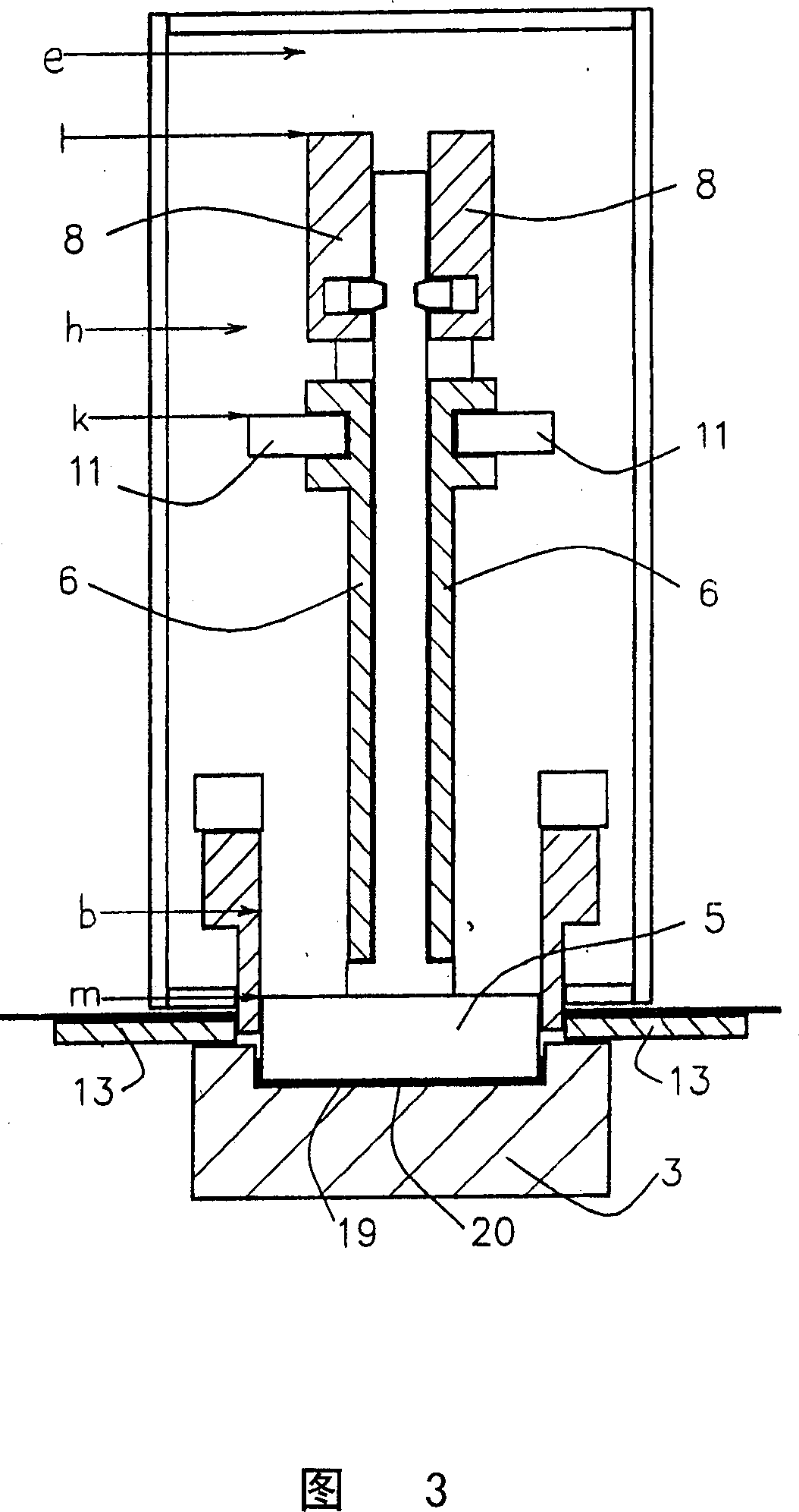
[0015] In order to explain the advantages of the present invention in detail, the steps involved in stamping and forming a container base for beverage containers will first be described according to FIGS. 1 to 3 . Then follow the instructions in Figure 4 to clean. For the sake of simplicity, only the essential parts of the stamping device 1 necessary for the description of the invention are shown schematically. As mentioned above, the following description refers only to the bottom of the container. However, these embodiments are also suitable for the top cap, which is usually punched out in a second such punching device in a plant for producing beverage cartons.

[0016] FIG. 1 shows the stamping device in the working position immediately before stamping. A punching belt 2 made of cardboard composite material is located between a bending mandrel 3 and the punching device 1 . The bending mandrel 3 , the drawing sleeve 13 and the stamping device 1 are axially aligned with on...


PUM


Abstract

In a process for cleaning a punching arrangement for punching out and forming a container bottom from a punching strip, a die is removed from its operational position for the purposes of cleaning and subsequently returned to its operating position. The die remains connected to the punching arrangement via a guiding element when removed from its operational position. The die can be withdrawn along the guiding element out of the punching arrangement. Furthermore, a punching arrangement is described in which the cleaning process can be very easily carried out.

Description

technical field [0001] The invention relates to a method for cleaning a stamping device for stamping and forming a container bottom or lid from a stamping band, in which a punch is removed from its working position for cleaning and then into its working position. [0002] The invention also relates to a stamping device for stamping and forming a container lid or bottom from a stamping belt, the device having a punch detachably fastened to a movable seat sleeve. Background technique [0003] Such stamping devices are used in industry in a wide variety of plants for processing strips of material. The stamping device can be used in particular in a machine in which a strip-shaped cardboard composite material is processed for a beverage container, in particular a paper cup or a substantially cylindrical beverage can. A blank is punched out by the punching device from the cardboard composite material fed in the form of a punching belt, which is usually in the form of a disc for ...

Claims


Application Information

Patent Timeline
Patent Type & Authority Applications(China)
IPC IPC(8): B31B43/00B31B50/59
CPCB26F1/44Y10T29/49815B26F1/40B26D7/088
Inventor U·默瑟施米德
Owner PTM PACKAGING TOOLS MACHINERY PTE
Why Eureka
Try Eureka