

Manual and automatic clutch structure of pneumatic actuator
A pneumatic actuator, manual and automatic technology, applied in the direction of engine components, mechanical equipment, valve operation/release devices, etc., can solve the problems of large manual torque and difficult operation, and achieve the effect of saving physical strength
- Summary
- Abstract
- Description
- Claims
- Application Information
AI Technical Summary
Problems solved by technology
Method used
Image

Examples
Embodiment Construction
[0020] It should be noted that, in the case of no conflict, the embodiments of the present invention and the features in the embodiments can be combined with each other.
[0021] The present invention will be described in detail below with reference to the accompanying drawings and examples.
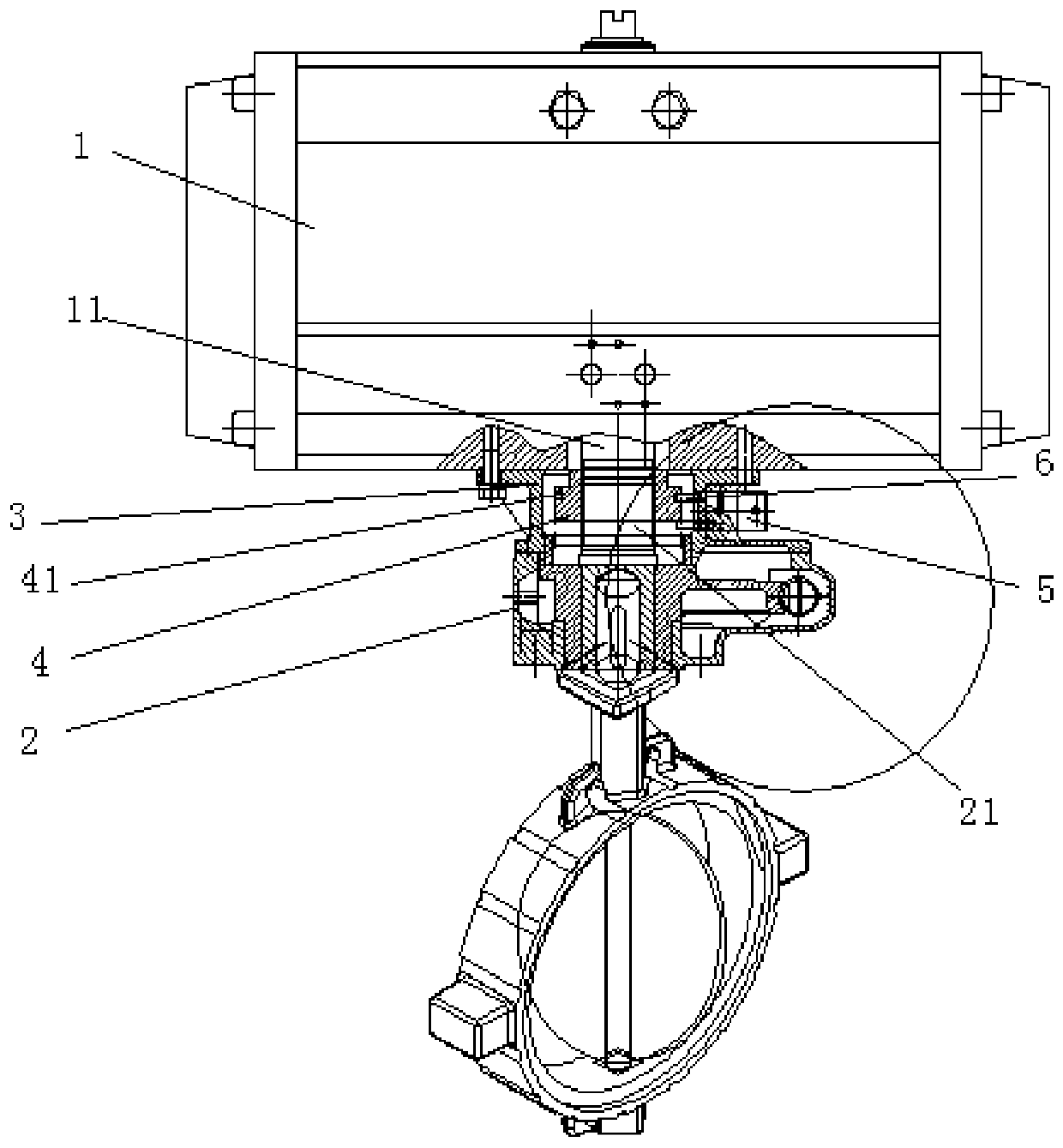
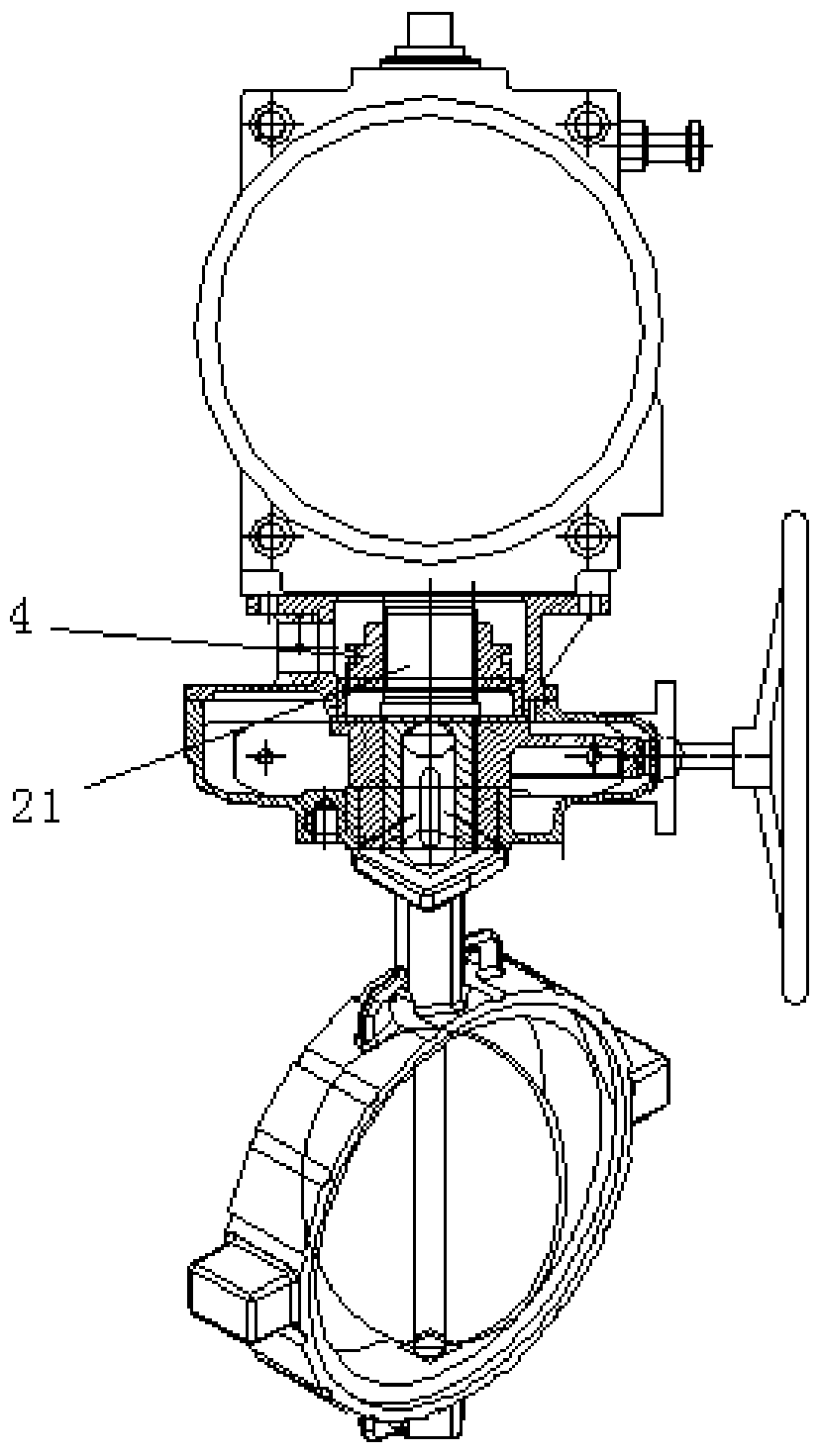
[0022] The manual automatic clutch structure of the pneumatic actuator includes a pneumatic actuator 1, a reducer mechanism 2, and a manual automatic clutch mechanism provided between the pneumatic actuator 1 and the reducer mechanism 2. The pneumatic actuator 1 includes an output shaft 11. The reducer mechanism 2 includes an input shaft 21 and a case cover 3, the output shaft 11 and the input shaft 21 are coaxially arranged, and the output shaft 11 and the input shaft 21 are respectively provided with external splines at corresponding ends, The box cover 3 is connected between the pneumatic actuator 1 and the reducer mechanism 2, the manual automatic clutch mechanism includes a sliding ...
PUM
 Abstract
Description
Claims
Application Information