Gas engine driven heat pump defrosting device

A gas engine, heat pump technology, applied in combustion engines, machines/engines, internal combustion piston engines, etc., can solve the problems of power consumption, limited heat, long defrosting time, etc., to improve the utilization rate of primary energy and enhance the utilization of waste heat. Effect

Inactive Publication Date: 2007-08-08
SOUTHEAST UNIV
View PDF0 Cites 19 Cited by
  • Summary
  • Abstract
  • Description
  • Claims
  • Application Information

AI Technical Summary

Problems solved by technology

There are obvious deficiencies in the reverse defrosting method: since the defrosting and heating are operated alternately, it leads to frequent start and stop of the compressor and switching of the four-way valve; during the defrosting process, the room does not supply heat, and even blows cold air; the defrosting takes up The time is long, resulting in a significant drop in the ambient temperature of the air conditioner during defrosting; during the switching process, there is mixing of cold and hot refrigerants, resulting in energy loss
[0004] Bypass defrosting is to open the bypass valve when defrosting is required, so that the high-temperature and high-pressure gas discharged from the compressor directly enters the heat exchanger of the outdoor unit for defrosting. The disadvantage of heat supply is also obvious: because only part of the refrigerant enters the outdoor heat exchanger coil, the heat is limited, resulting in slower defrosting and longer defrosting time
[0005] The above two defrosting devices belong to the defrosting device of the electric-driven air source heat pump. They both use the system heat generated by the compressor to defrost. There is no other heat supplement during the period, and the defrosting requires a lot of heat, so the overall effect is less
At present, there are measures to use other heat energy to defrost, such as the use of electric heating tubes. Although this method can improve the defrosting effect, it increases the cost of components and consumes a lot of electric energy.

Method used


Image

  • Gas engine driven heat pump defrosting device

Examples


Embodiment Construction

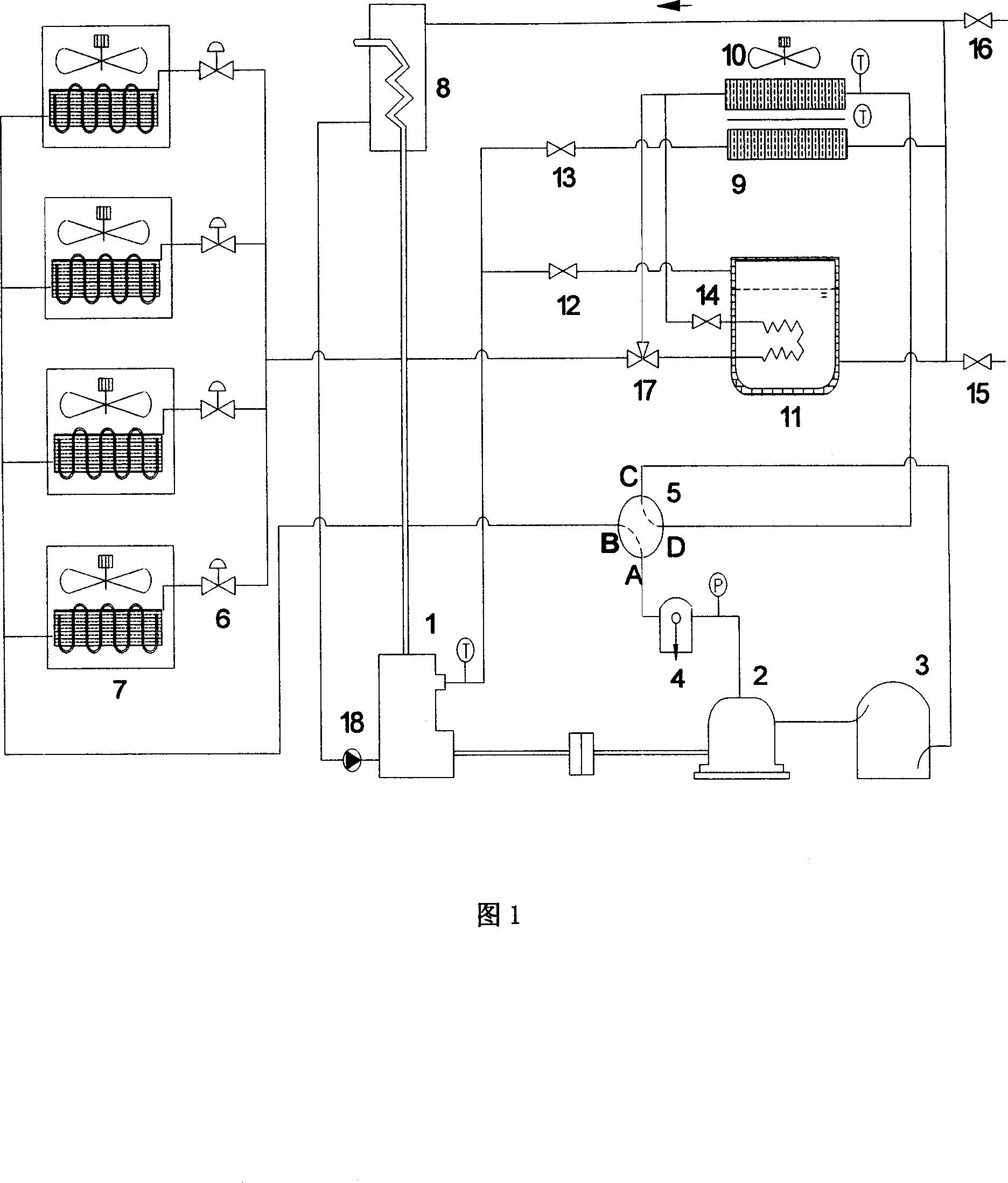
[0020] As shown in Figure 1, the gas engine-driven heat pump novel defrosting device of the present invention includes a heating defrosting circulation system, a cooling water circulation system and a control system; the heating defrosting circulation system is connected with the cooling water tank 11 The water circulation system is connected, and the heating and defrosting circulation system and the cooling water circulation system are connected with the control system through a circuit.

[0021] The heating and defrosting cycle system is composed of a gas engine 1, a compressor 2, a gas-liquid separator 3, an oil separator 4, a four-way valve 5, an electronic expansion valve 6, an indoor heat exchanger 7, and an outdoor heat exchanger. Device 10, heat preservation water tank 11, third shut-off valve 14 and three-way valve 17 etc. are connected by pipeline and form.

[0022] The cooling water circulation system is composed of a first stop valve 12, a second stop valve 13, a h...


PUM


Abstract

The invention relates to a heat pump defrost device driven by the gas turbine, which can combine the abundant heat utilization and the heat pump defrost techniques. The invention comprises a heating defrost circulator, a cooling water circulator and a control system, wherein, the defrost circulator via the thermal-insulated water box is connected with the cooling water circulator; and the defrost circulator and the cooling water circulator are connected with the control system electrically. In the defrost process, the invention recycles the heat of engine and discharge smoke, via the water circulator to be stored in the thermal-insulated water box, to utilize the energy of stored hot water of water box to defrost. And in the defrost process, the four-way valve is not steered, to avoid affecting the indoor heat supply. The invention can supply hot water at 70Deg. C without defrosting.

Description

technical field [0001] The invention relates to a novel defrosting device for a heat pump air-conditioning unit driven by a gas engine, belonging to the technical field of refrigeration and air-conditioning. Background technique [0002] During the heating process of the air source heat pump unit, when the temperature of the heat exchanger coil of the outdoor unit is lower than the air dew point temperature, condensed water will be generated on the surface, and once the condensed water is lower than 0°C, frost may form. When the frost is severe, the air passage between the fins of the outdoor unit heat exchanger is partially or completely occupied by frost, which increases the thermal resistance and wind resistance, which will directly affect the heat exchange efficiency of the outdoor unit heat exchanger. Frosting is an inevitable phenomenon in the heat supply process of heat pump air conditioners. Therefore, it is necessary to install a defrosting device in the air source ...

Claims


Application Information

Patent Timeline
Patent Type & Authority Applications(China)
IPC IPC(8): F25B47/02F02G5/02
CPCY02T10/166Y02P80/15Y02T10/12
Inventor 李应林张小松
Owner SOUTHEAST UNIV
Why Eureka
Try Eureka