
Light-control sheet and surface illuminant unit

A technology of light control and surface light source, applied in light guides, optics, optical components, etc., can solve the problems of increased light leakage, poor light utilization efficiency, and sharp changes, and achieve the effect of preventing uneven brightness

Inactive Publication Date: 2010-12-15
DAI NIPPON PRINTING CO LTD
View PDF9 Cites 0 Cited by
  • Summary
  • Abstract
  • Description
  • Claims
  • Application Information

AI Technical Summary

Problems solved by technology

However, the film with triangular prisms described in Japanese Unexamined Patent Publication No. 63-318003 has a second brightness peak in the direction of a large emission angle of about 60 to 80 degrees in addition to the brightness peak near the emission angle of 0 degrees. When displaying, there is a problem that more light leaks and the contrast deteriorates
Furthermore, in the film having triangular prisms described in JP-A No. 63-318003, there is a problem that the viewing angle characteristics change rapidly at both the vertical viewing angle and the horizontal viewing angle, and the luminance changes drastically.
[0010] In addition, conventional surface light source devices have emission characteristics that maintain a peak in the normal direction of the emission surface of the surface light source, and the viewing angle characteristics cannot be said to be most suitable for applications such as televisions that are often viewed from the front to the top. There is a problem of poor light utilization efficiency

Method used


Image

  • Light-control sheet and surface illuminant unit
  • Light-control sheet and surface illuminant unit
  • Light-control sheet and surface illuminant unit

Examples


Embodiment Construction

[0048] Hereinafter, embodiments of the present invention will be described in detail with reference to the drawings. In the drawings, the size and shape of each component are appropriately exaggerated for easy understanding.

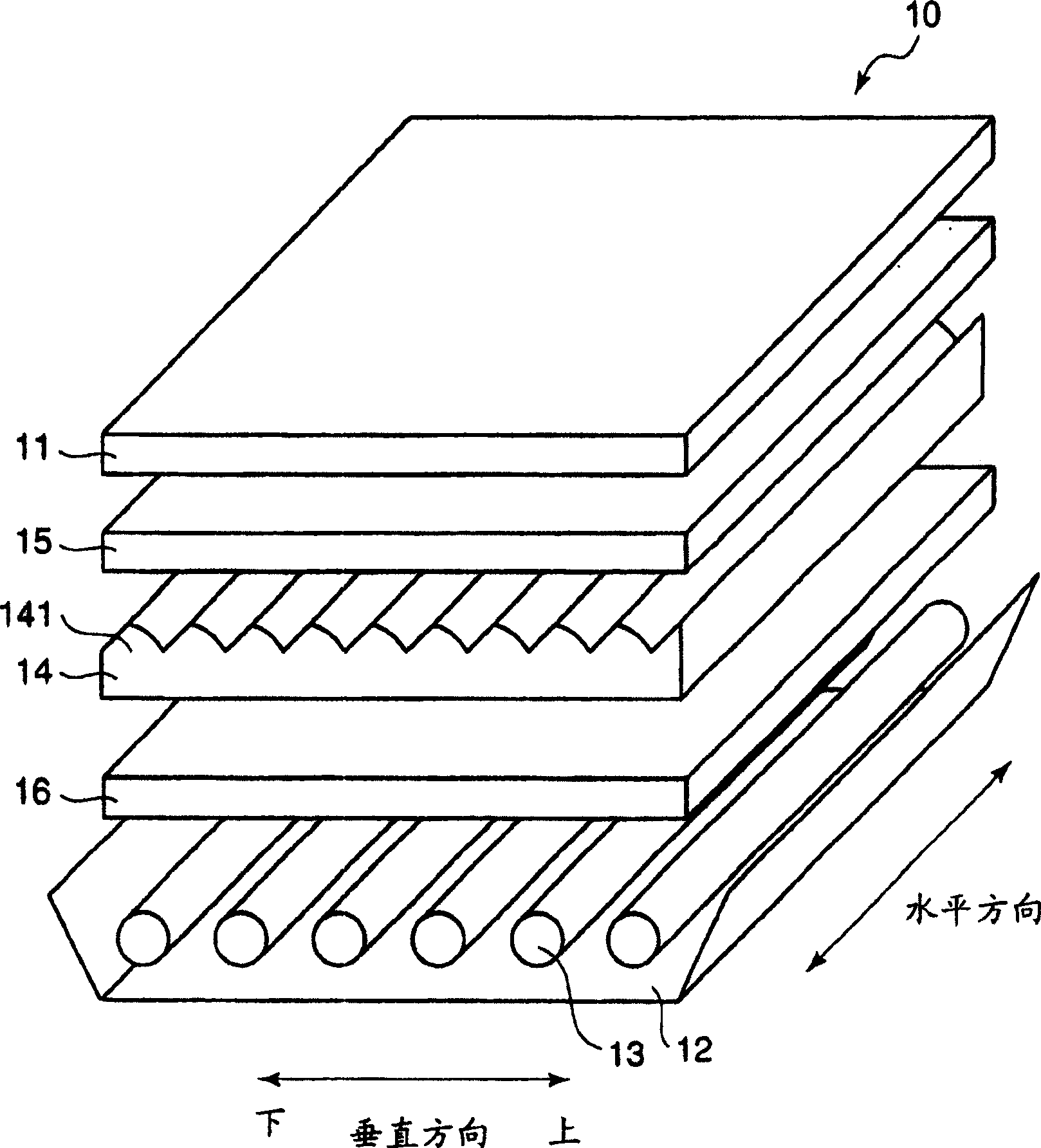
[0049] figure 1 It is an exploded perspective view showing the first embodiment of the transmissive display device of the present invention. Such as figure 1 As shown, the transmissive display device 10 has an LCD panel 11 , a reflective plate 12 , a light emitting tube 13 , a light control sheet 14 , a reflective polarizer 15 and an opalescent plate 16 .

[0050] The transmissive display device 10 is a device that illuminates and displays image information formed on the LCD panel 11 from the back of the LCD panel 11 . The surface light source device for illuminating the LCD panel 11 from the back includes: a reflector 12 , a light emitting tube 13 , a light control sheet 14 , a reflective polarizer 15 and an opalescent plate 16 .

[0051] The LCD pa...


PUM

PropertyMeasurementUnit
thicknessaaaaaaaaaa
refractive indexaaaaaaaaaa

Abstract

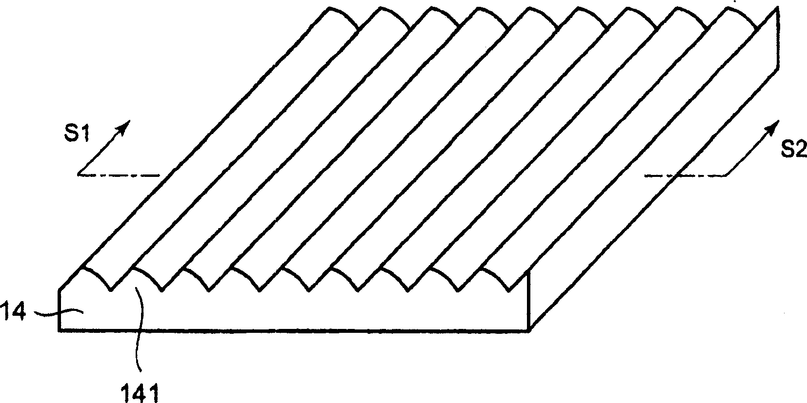
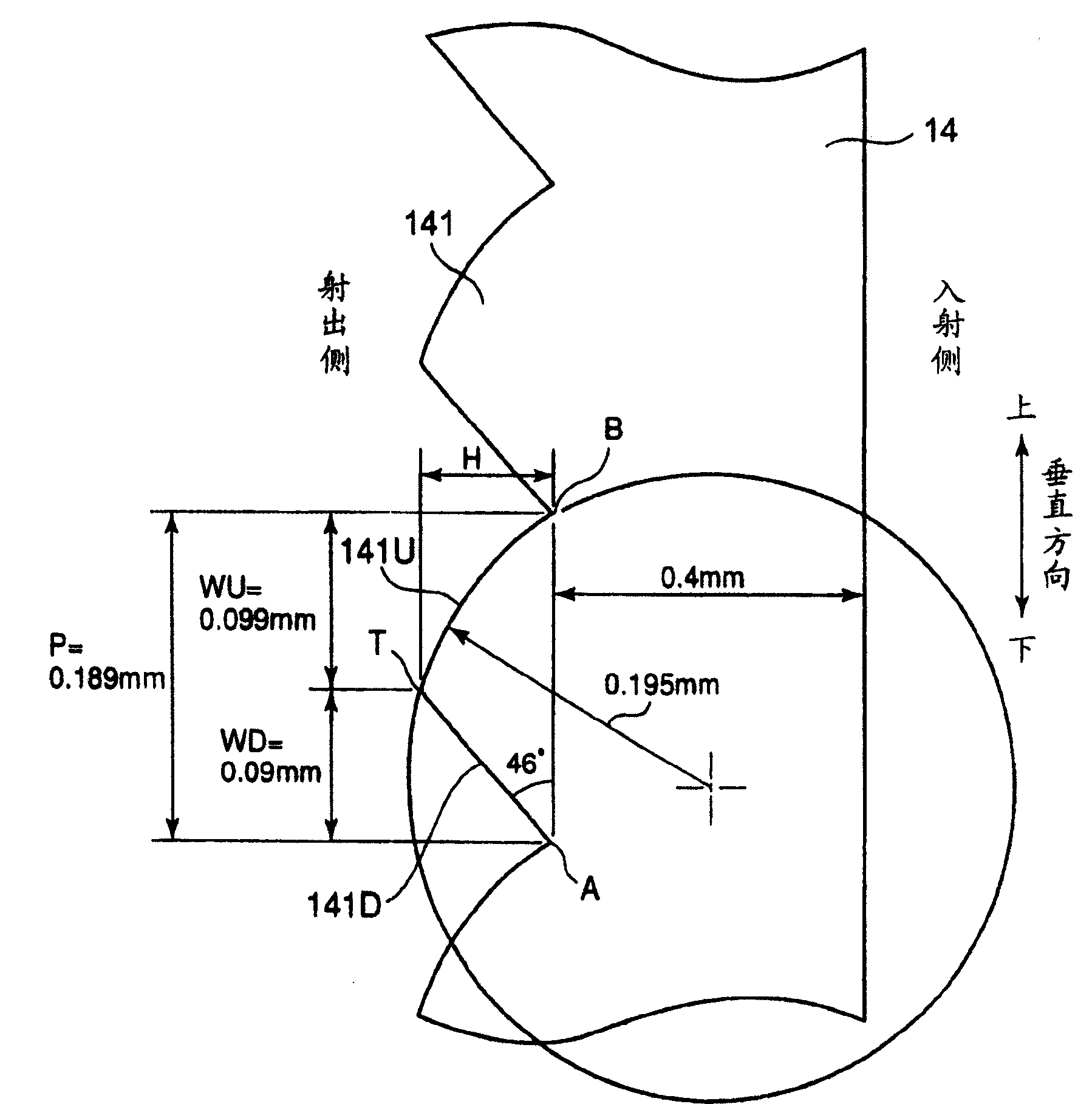
The present invention is a light-controlling sheet for making light emitted from light sources uniform and / or converging the light. The light-controlling sheet includes a lens part having a large number of rod-like unit lenses arranged in parallel, with a lens surface of each unit lens facing to the light-exiting side. A cross section of the lens surface of each rod-like unit lens taken perpendicularly to the longitudinal direction of the unit lens is asymmetrical. The lens surface of each unit lens has a flat surface part in the shape of a flat surface, and a curved surface part in the shapeof part of a cylindrical surface.

Description

technical field [0001] The present invention relates to a light-controlling sheet and a surface light source device used for lighting such as a liquid crystal display device. Background technique [0002] As a surface light source for illuminating a transmissive liquid crystal display or the like from the back, various types of surface light source devices have been proposed and put into practical use. In surface light source devices, there are mainly edge-light type and direct-light type. This is different in the way a light source that is not an area light source is transformed into an area light source. [0003] For example, in a direct-type surface light source device, light is introduced from the back side using parallel cold-cathode tubes. Appropriately leave the distance between cold cathode tubes and transmissive display elements such as LCD panels, use a diffuser plate between them, and use a combination of multiple light-condensing plates. [0004] In such a con...

Claims


Application Information

Patent Timeline
Patent Type & Authority Patents(China)
IPC IPC(8): G02B6/00G02B3/00G02F1/1335
Inventor 儿玉大二郎后藤正浩德原渡
Owner DAI NIPPON PRINTING CO LTD
Learn More