
LED (Light Emitting Diode) dimming device, system and method

A LED lamp and LED drive technology, applied in the field of LED lighting, can solve the problems of inability to adjust the brightness of LED lamps, the process of LED dimming is not stable enough, and the range of PWM count value changes is large, so as to make up for the limitations of heat dissipation , Brightness changes smoothly, and the effect of precise adjustment

Inactive Publication Date: 2015-02-11
SEKORM ADVANCED SHENZHEN TECH CO LTD
View PDF2 Cites 0 Cited by
  • Summary
  • Abstract
  • Description
  • Claims
  • Application Information

AI Technical Summary

Problems solved by technology

The traditional LED dimming process uses the temperature of the fixed LED lamp as a variable to correspond to the pulse width modulation (PWM) count value. When the temperature of the LED lamp changes to a different preset fixed temperature point, the PWM count The magnitude of the value change will be large, resulting in a relatively obvious step-wise change in the brightness of the LED light
[0004] Therefore, the traditional LED dimming method has the disadvantage that the brightness of the LED lamp cannot be adjusted accurately according to the temperature of the LED lamp, and the process of LED dimming is not stable enough.

Method used


Image

  • LED (Light Emitting Diode) dimming device, system and method
  • LED (Light Emitting Diode) dimming device, system and method
  • LED (Light Emitting Diode) dimming device, system and method

Examples


Embodiment Construction

[0050] The present invention will be further explained below with reference to the drawings and embodiments.

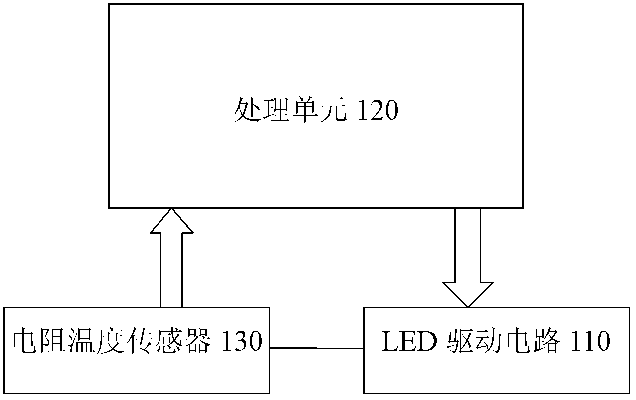
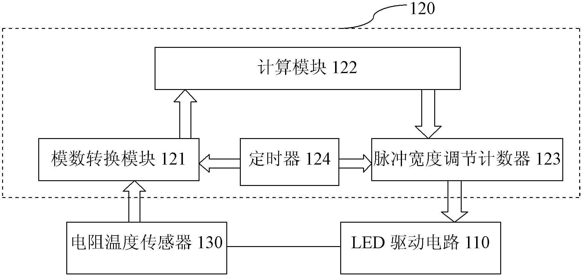
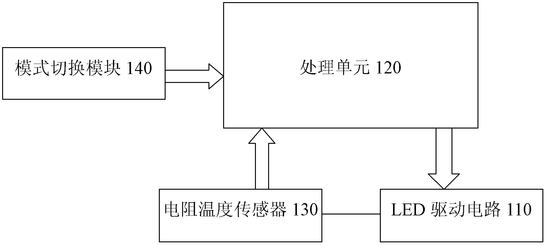
[0051] figure 1 It is a structural block diagram of the first embodiment of the LED dimming system of the present invention, such as figure 1 As shown, in this embodiment, the LED dimming system of the present invention includes an LED driving circuit 110; the LED driving circuit 110 includes an LED lamp and a switch tube that controls the average current of the LED lamp; the system also includes a processing unit 120, and Resistance temperature sensor 130 connected in series with the LED lamp;

[0052] Among them, the processing unit 120 periodically collects the partial pressure value of the resistance temperature sensor 130 at the current temperature, performs analog-to-digital conversion of the collected multiple partial pressure values, and averages them to generate the digital signal AD_Value at the current temperature. Convert the generated digital signal AD_Value a...


PUM


Abstract

The invention provides an LED (Light Emitting Diode) dimming device, a system and a method. The method includes the following steps that: collecting the partial pressure values of a resistance temperature sensor; conducting analog-to-digital conversion to the collected partial pressure values, and averaging the partial pressure values to generate a digital signal AD_Value (analog-to-digital); and calculating the corresponding pulse width modulation value PWM_Value( Pulse-Width Modulation) according to a formula so as to adjust the duty ratio of an outputted pulse width modulation signal. In such a way, precise adjustment to the average current of a loaded LED light is realized, and the brightness of the LED light changes smoothly. The method for automatically, dynamically and precisely adjusting the brightness of the LED light so as to adjust the temperature of the LED light offsets the limitation of the heat dissipation of the hardware of the LED light.

Description

Technical field [0001] The present invention relates to the field of LED lighting, and more specifically, to an LED dimming device, an LED dimming system and an LED dimming method. Background technique [0002] As a brand-new lighting technology, LED lighting has attracted worldwide attention and is known as the third revolution in the history of human lighting. High-brightness LED lights can provide higher brightness with less power consumption, and have the advantages of energy saving, environmental protection, shock resistance, long service life and fast switching on. The LED lamp is a typical current-driven device. Due to its own voltage drop, people pay more and more attention to heat dissipation in the lighting applications of high-power LED lamps. This is because the light decay of the LED or its life is directly related to its junction temperature. If the heat dissipation is not good, the junction temperature will be high and the life will be short. According to the Arrh...

Claims


Application Information

Patent Timeline
Patent Type & Authority Patents(China)
IPC IPC(8): H05B37/02
CPCY02B20/42Y02B20/40
Inventor 杨波孙旭辉
Owner SEKORM ADVANCED SHENZHEN TECH CO LTD
Learn More