
Illumination device and liquid crystal display device

一种照明装置、照射区域的技术,应用在照明装置、照明和加热设备、光学等方向,能够解决亮度不均等问题,达到提高画质的效果

Inactive Publication Date: 2010-06-23
SHARP KK
View PDF8 Cites 0 Cited by
  • Summary
  • Abstract
  • Description
  • Claims
  • Application Information

AI Technical Summary

Problems solved by technology

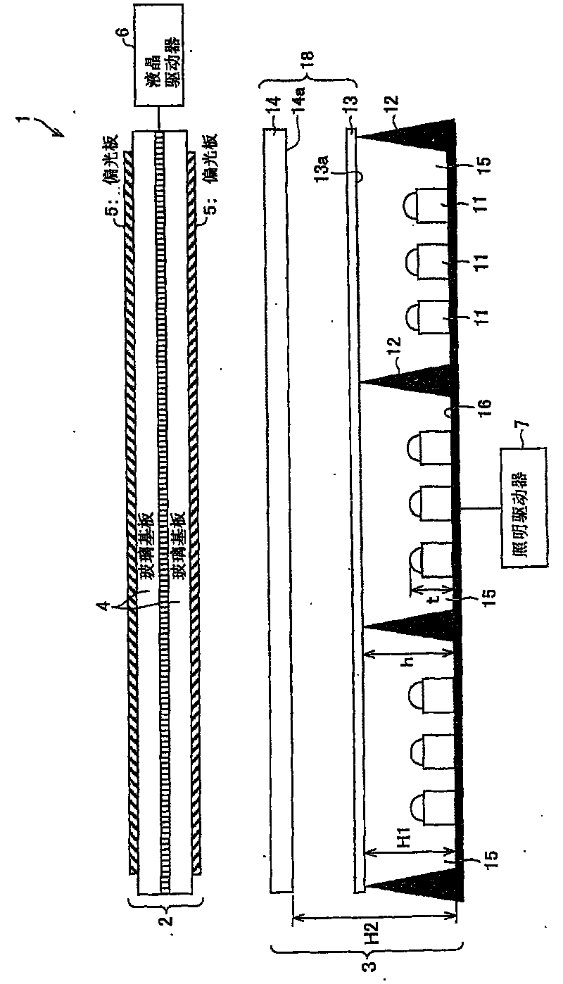
[0012] However, in such a structure having a plurality of light sources 131 in one lighting area 134, if the height h of the partition wall 132 dividing each lighting area 134 is close to the height H at which the light diffusing sheet 133 is arranged, then at the same brightness point When the entire illumination area 134 is brightened, the portion corresponding to the partition wall 132 becomes a dark portion, resulting in uneven brightness.

Method used


Image

  • Illumination device and liquid crystal display device
  • Illumination device and liquid crystal display device
  • Illumination device and liquid crystal display device

Examples


Embodiment approach 2

[0093] Below, according to Figure 7 , Figure 8 , Describes other embodiments of the present invention.

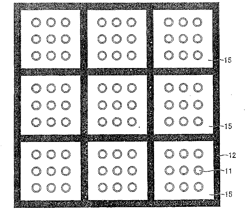
[0094] Figure 7 It is a schematic diagram showing the configuration of the main part of the backlight device in the liquid crystal display device of this embodiment, Figure 8 It is a plan view of the main part of the backlight device 8.

[0095] The liquid crystal display device of the second embodiment is different from the liquid crystal display device 1 of the first embodiment in that a backlight device 8 is provided instead of the backlight device 3, and the difference between the backlight device 3 and the backlight device 8 is that they are arranged on the light source arrangement surface Light source on 16.

[0096] That is, a plurality of white light sources 11 are provided in the backlight device 3. However, in the backlight device 8, such as Figure 8 As shown, a plurality of red light sources 11R, green light sources 11G, and blue light sources 11B are respectively ...

Embodiment 1

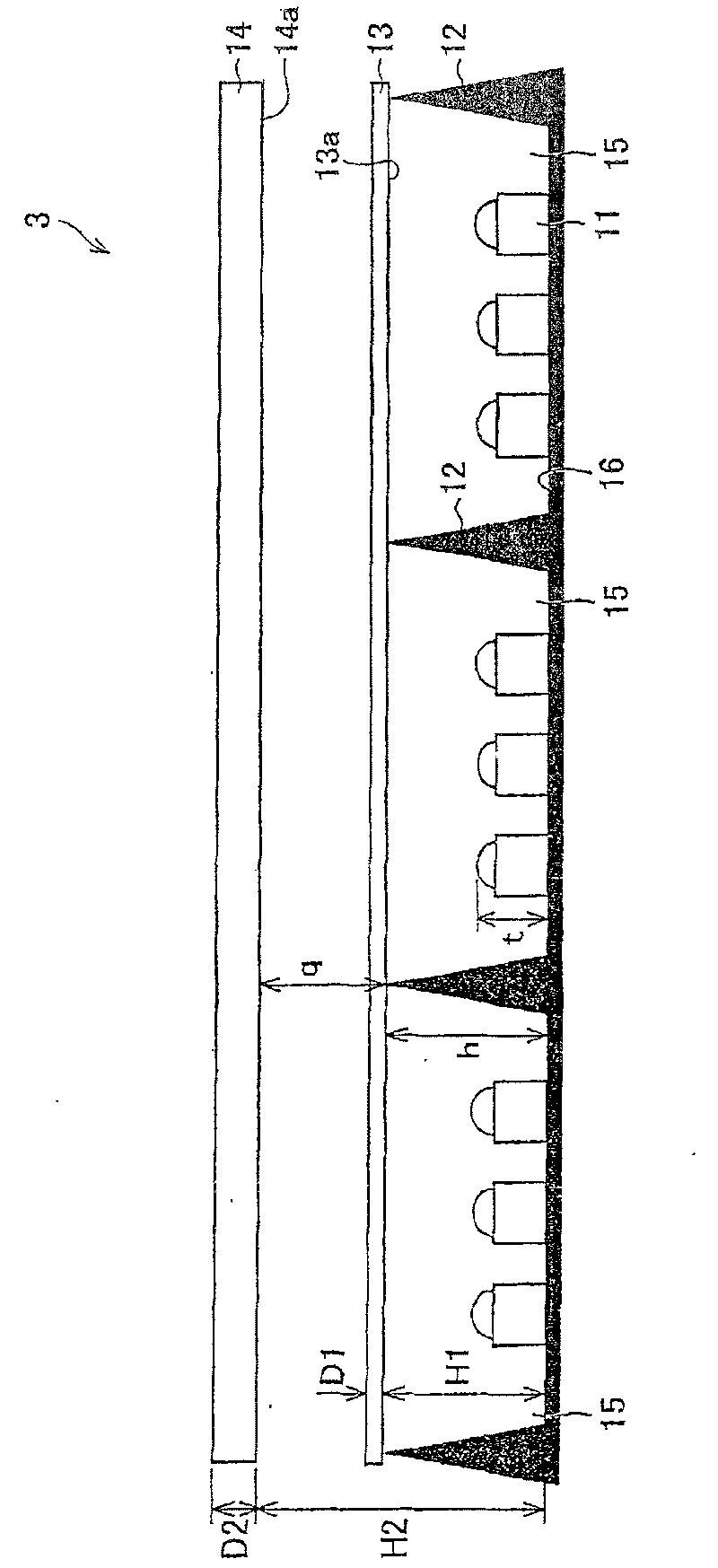
[0110] Next, an example of the backlight device 3 of Embodiment 1 will be described. In the structure of the aforementioned backlight device 3, as the plurality of light sources 11, (model number) NCCW022S manufactured by Nichia Chemical Co., Ltd. is used. The size of the light source is 10mm in the middle and 10mm in height. In addition, as the first light diffusing member 13, (product name) Opals (オパルス) BS-01 manufactured by Ewa Co., Ltd. was used, and as the second light diffusing member 14, Nitto Plastics Co., Ltd. was used. (Product name) CLAREX DR-IIIC DR-60C. The thickness D1 of Opals BS-01 used as the first light diffusion member 13 is 0.125 (mm), and the haze ratio is 87 (%). On the other hand, the thickness D2 of the CLAREX DR-IIICDR-60C used as the second light diffusion member 14 is 2.0 (mm), and the haze ratio is 96 (%).

[0111] In addition, the height h of the partition wall 12 from the light source arrangement surface 16 is 25 (mm), and the first light diffusio...

Embodiment 2

[0115] Next, other examples of the backlight device 3 in Embodiment 1 will be described. The difference from Embodiment 1 is the arrangement height of the first light diffusion member 13. Here, such as Picture 10 As shown, the light incident surface 13a of the first light diffusion member 13 is arranged at a position lower than the vertex of the partition wall 12. The height h of the partition wall 12 from the light source arrangement surface 16 is 25 (mm). In contrast, from the light source arrangement surface The height H1 from 16 to the light incident surface 13a of the first light diffusion member 13 is 20 (mm). The height q (q=H2-h) of the second light diffusion member 14 from the vertex of the partition wall 12 to the light incident surface 14a is 15 (mm).

[0116] As in Example 1, in this case, since the light from each light source 11 in the illuminated area 15-1 in the bright state has the same projection area S'in the first light diffusion member 13, it is projected o...


PUM


Abstract

The invention relates to an illumination device and a liquid crystal display device. In a backlight device (3) placed layered on a liquid crystal panel (2), light sources (11) are partitioned into illumination regions (15) by partition walls (12), a first light diffusion member (13) is placed over the light source, and second light diffusion member (14) is layered on the first light diffusion member (13). The first light diffusion member (13) is placed such that a light incident surface (13a), into which light from each light source (11) enters, is located at a position that is higher than the light sources (11) and at the same height as or lower than the vertexes of the partition walls (11). The second light diffusion member (14) is placed over the first light diffusion member (13) with a gap in between and with a light incident surface (14a) placed at a position higher than the vertexes of the partition walls (12). In the backlight device that is partitioned into the illumination regions and where the light sources are arranged in each of the illumination regions, each illumination region can be independently controlled without reducing performance as the illumination device.

Description

Technical field [0001] The present invention relates to a lighting device having a plurality of light sources and a liquid crystal display device including the lighting device as a backlight device. Background technique [0002] Liquid crystal display devices have the characteristics of thinness, low power consumption, and high definition. With the increase in screen size brought about by the development of manufacturing technology, they have evolved to the existing cathode-ray tube (CRT)-based televisions. Began to spread in the field. [0003] However, the image displayed in the liquid crystal display device has some problems in terms of image quality due to its display method, such as low contrast (dynamic range) compared to CRT images, and blurred images during animation. Therefore, in recent years, technological development related to improving image quality is booming. [0004] For example, Patent Document 1 discloses a liquid crystal display device that controls the brightne...

Claims


Application Information

Patent Timeline
Patent Type & Authority Patents(China)
IPC IPC(8): F21S2/00G02F1/13357F21Y101/02
CPCG02F1/133606G02F1/133603G02F1/133608G02F2001/133601G02F1/133601
Inventor 增田岳志田中敦幸角田行广
Owner SHARP KK
Learn More