
U-shaped clamp

A clamp, U-shaped technology, applied in the field of U-shaped clamps, can solve the problems of difficult insertion and screwing of alignment bolts, limit the stability of the connection, etc., and achieve the effect of improving maneuverability

Active Publication Date: 2007-08-15
EJOT GMBH & CO KB
View PDF4 Cites 13 Cited by
  • Summary
  • Abstract
  • Description
  • Claims
  • Application Information

AI Technical Summary

Problems solved by technology

This leads to the following disadvantage especially in the case of thin sheet metal parts: the bent legs only contact some points in the area, and in any case not contact the stretched area, which significantly limits the plate carrying the clip and the plate to be fixed to the plate. The stability of the connection between the components on the
Such loose mounting of the nut part has the danger that the loose fork or hook connection between the clip and the yoke will tilt, thus making it more difficult to require alignment for the bolt to be inserted and screwed in

Method used


Image

  • U-shaped clamp
  • U-shaped clamp
  • U-shaped clamp

Examples


Embodiment Construction

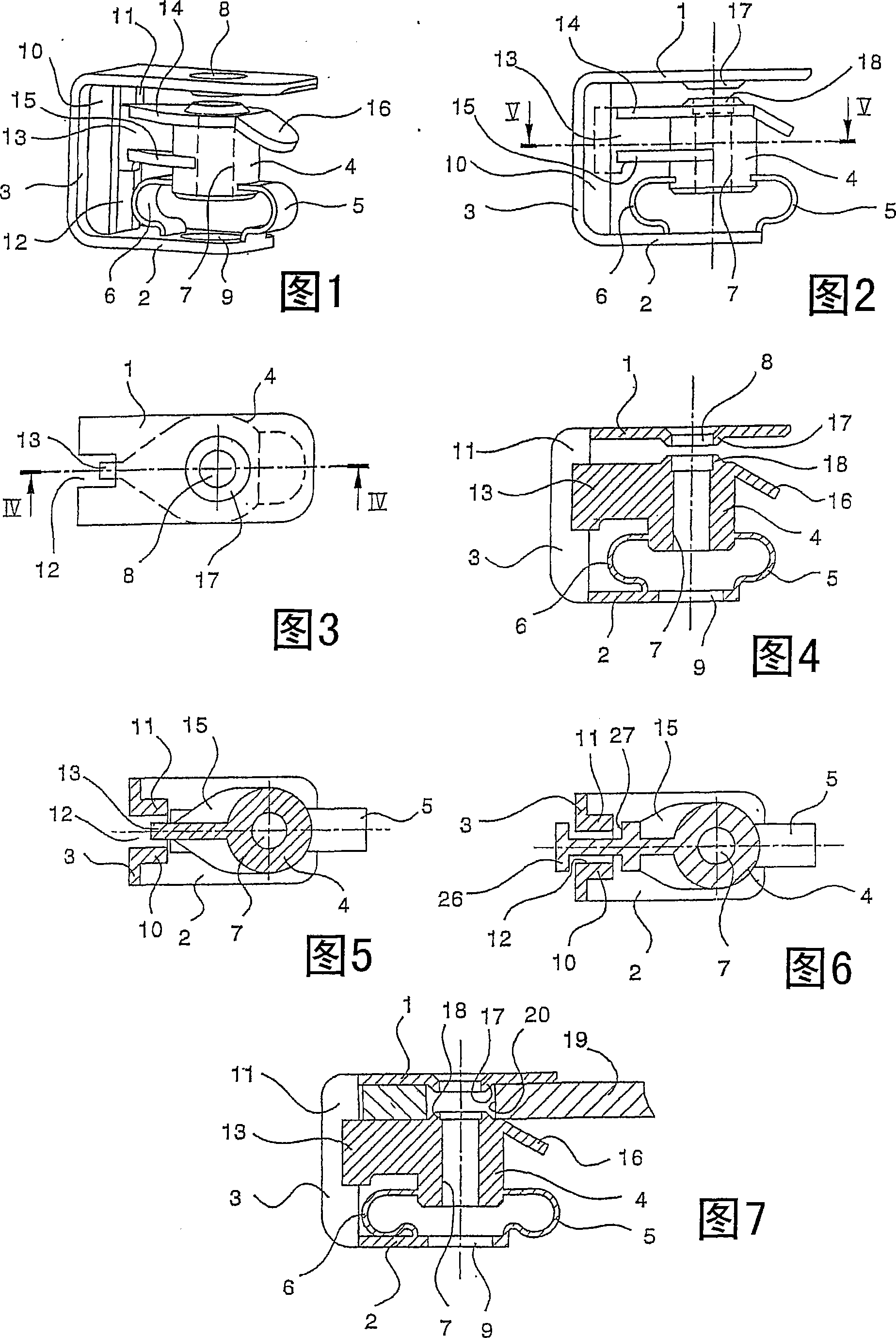
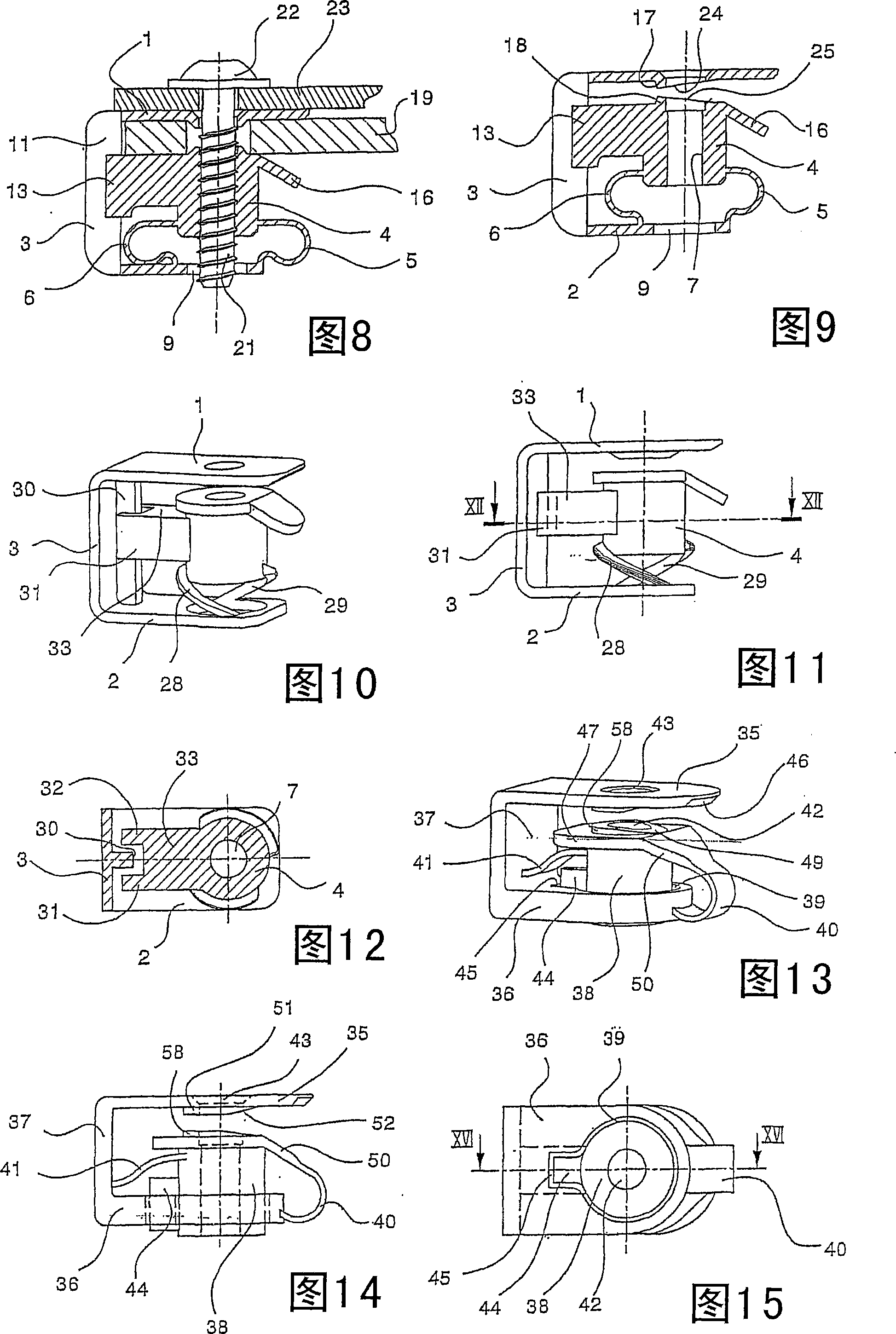
[0045]The clamp shown in the perspective view of FIG. 1 comprises an upper leg 1 , a lower leg 2 and a yoke 3 connecting the two legs 1 and 2 . The clamp is made of a material that allows the two legs 1 and 2 to bend relative to the yoke 3 and then elastically return when the plate is inserted into the clamp (this will be explained in conjunction with FIGS. 7 and 8 ).

[0046] Arranged between the two legs 1 and 2 is a nut part 4 integrally connected to the leg 2 via arcuate bands 5 and 6 . The straps 5 and 6 are likewise made of elastic material and provide the nut part 4 with respect to the movability in the axial direction relative to the nut part 4 . The nut part 4 contains a hole 7 into which a bolt can be screwed, as shown in conjunction with FIG. 8 . In order to be able to introduce a screw into the nut part 4 , the leg 1 is provided with a hole 8 . The legs 2 also have similar holes 9 so that the entire clamp can be threaded by a bolt (see FIG. 8 ). Since a torque i...


PUM


Abstract

The invention relates to a U-shaped clamp for attaching to plate, has opening. The clamp has an opening. The clamp has two flat limbs which are connected by a bracket and a nut which can be moved axially between the two limbs and is designed to receive a screw that passes through the opening and one limb. The nut is held on the clamp so that it is secured against rotation by a lateral arm. The nut is fixed at its end in an axially sprung manner to the limb facing away from the plate by several clasps running from the end of the nut part to the limb.

Description

technical field [0001] The invention relates to a U-shaped clamp for connecting plates, wherein the plates are provided with openings, the clamp has two flat legs connected by a yoke and a nut part axially movably arranged in Between the two legs is intended to receive a bolt passing through the opening and one leg, wherein the nut part is held non-rotatably on the clamp by the lateral arm. Background technique [0002] The purpose of such clamps is to fix the part to the plate by means of bolts, which requires that the plate be provided with nut parts to receive the bolts, since generally the plates themselves are not suitable to accommodate the threads into which the bolts can be screwed. The clamp allows the nut part to be placed in the region of the opening in the panel, as a result, the component can then be screwed into the panel by means of the bolt and nut part. [0003] In this regard, reference is made to European patent specification 0 353 468 B1 which discloses ...

Claims


Application Information

Patent Timeline
IPC IPC(8): F16B37/04
CPCF16B37/005F16B5/0266F16B37/044
Inventor 乌韦・劳茨马可・戈林埃伯哈・克里斯特
Owner EJOT GMBH & CO KB
Learn More