Passenger transmitter

A technology of passenger conveying equipment and pedals, which is used in transportation and packaging, escalators, etc., can solve the problems of passengers' riding comfort, and achieve the effect of comfortable riding.

Inactive Publication Date: 2007-08-29
HITACHI LTD
View PDF1 Cites 5 Cited by
  • Summary
  • Abstract
  • Description
  • Claims
  • Application Information

AI Technical Summary

Problems solved by technology

Therefore, vibrations caused by the engagement between the pedal drive sprocket and the pedal chain and the rotation of the pedals may still be transmitted to the frame through the pedal drive sprocket
[0005] Especially recently, due to the revision of the Enforcement Order of the Building Standards Act, etc., the restrictions on the running speed of the electric passage have been eased. Vibration will reach a level that cannot be ignored. If the vibration is transmitted to the frame, it will have a great impact on the comfort of passengers

Method used


Image

  • Passenger transmitter
  • Passenger transmitter
  • Passenger transmitter

Examples


Embodiment Construction

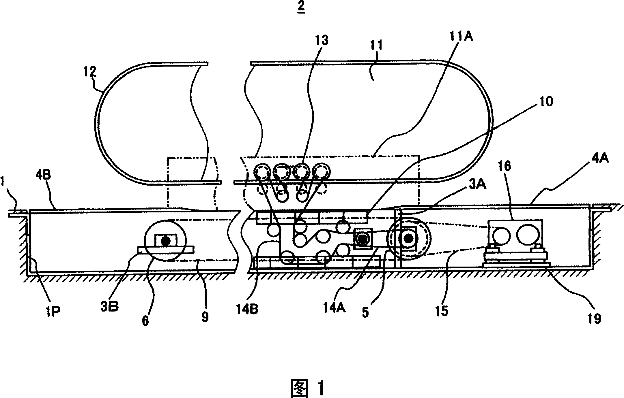
[0044] First, the electric channel 2 in this embodiment is the same as the existing electric channel shown in Fig. 1 and Fig. 2, and has the following structure.

[0045] The motorized tunnel 2, which is one type of passenger conveyance equipment, has a frame formed by a frame body 3 housed in a pit 1P formed on the floor surface 1 of the building, and main equipment is installed in the frame body 3. In addition, on the upper parts of both ends of the frame body 3 in the longitudinal direction, landing floors 4A, 4B flush with the floor surface 1 are respectively provided, and the pedal driving sprocket 5 and the pedal driven sprocket 6 are pivotally supported on these landing floors. Near the lower part of the drop floor 4A, 4B.

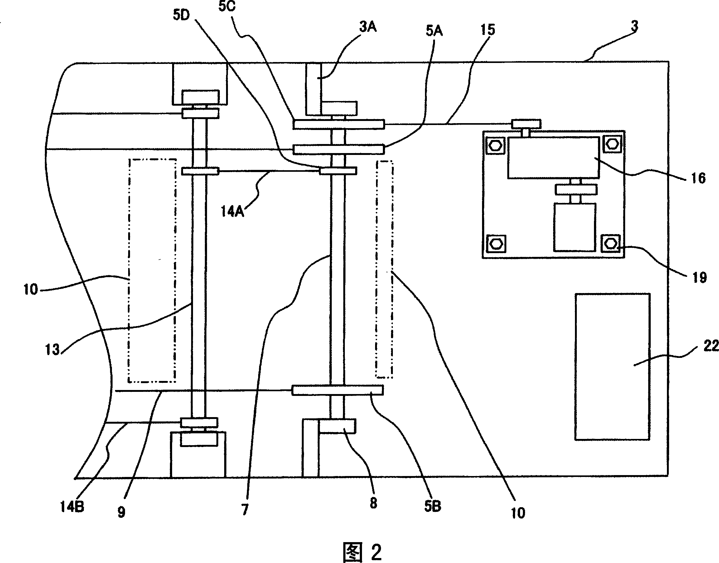
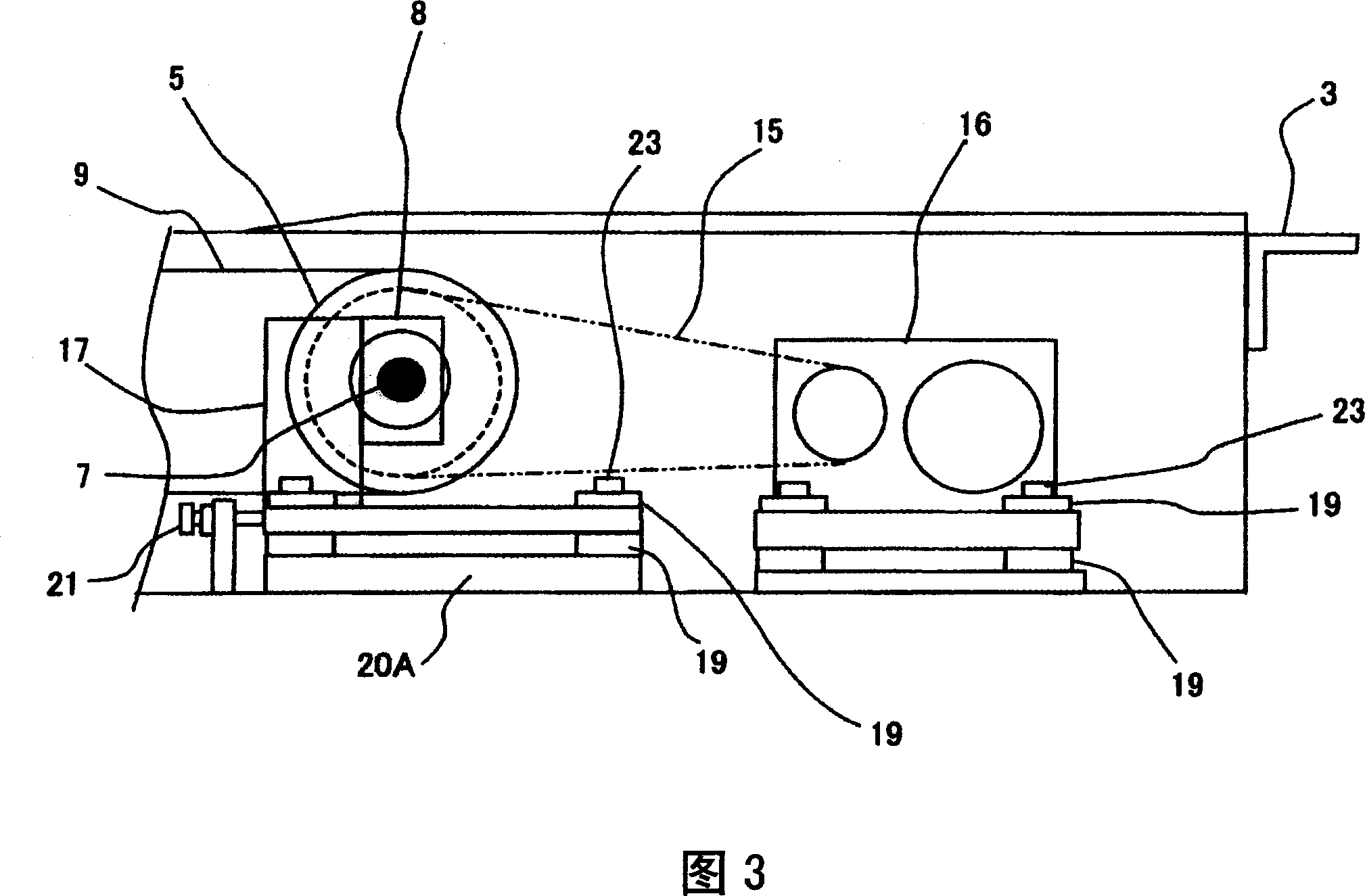
[0046] Here, the pedal drive sprocket 5 has a pair of pedal drive sprockets 5A, 5B fixedly spaced apart on the drive shaft 7, and one of the pedal drive sprockets 5A is provided on the inner side in the width direction with a pin coaxial with the pe...


PUM


Abstract

The present invention provides a passenger conveying device capable of suppressing transmission of vibration of a drive sprocket to a main frame and having a comfortable ride. The passenger conveying equipment includes: a frame body (3), which is provided with landing floors (4A, 4B) on the upper parts of both ends in the longitudinal direction; a pair of pedal driving sprockets (5) and a pedal driven sprocket (6). , which are respectively pivotally supported in the vicinity of the below of the landing floors (4A, 4B) in the frame (3); pedal chains (9), which are wound around these pedal drive sprockets (5) and the pedals from between the movable sprockets (6); a plurality of pedals (10) linked with the pedal chains (9); and a mobile handrail (12) that moves cyclically synchronously with these pedals (10), wherein the pedals The drive sprocket (5) is supported by a base (17) fixed on the bottom of the frame (3).

Description

technical field [0001] The present invention relates to passenger conveying equipment such as motorized walkways and escalators for conveying passengers. Background technique [0002] In conventional passenger conveyors, the pedal driving sprocket is directly fixed to a frame extending in the longitudinal direction formed by skeletons such as an upper string member and a lower string member (see FIGS. 1 and 2 ). In addition, a method is described in the following Patent Document 1, in which, in order to prevent the vibration and noise of the driving machine from being transmitted along the frame and adversely affecting the ride comfort of the escalator and the building, sandwiching Anti-vibration rubber set drive machine. [0003] Patent Document 1: Microfilm No. 58-14794, Japanese Patent Application Laid-Open (Claims, Figures 1 to 4, etc.) [0004] However, in the above-mentioned Patent Document 1, the pedal drive sprocket is directly fixed to the frame as in the conventi...

Claims


Application Information

Patent Timeline
IPC IPC(8): B66B23/02
Inventor 宇津宫博文阿部义雄五味雅志
Owner HITACHI LTD
Why Eureka
Try Eureka