Cast-in-situ concrete hollow board

A technology of hollow slab and cast-in-place concrete, which is applied in the direction of floor slabs, building components, buildings, etc., can solve the problem of inability to effectively ensure the uniform design width of hidden ribs in the floor, the inability to ensure the pouring quality of cast-in-place concrete hollow slabs, and building components. Inconvenient lateral limit and other problems, to achieve the effect of ensuring pouring quality, high rigidity, and excellent anti-vibration performance

Inactive Publication Date: 2007-08-29
湖南邱则有专利战略策划有限公司
View PDF2 Cites 5 Cited by
  • Summary
  • Abstract
  • Description
  • Claims
  • Application Information

AI Technical Summary

Problems solved by technology

However, when this building component is applied to the cast-in-place concrete hollow floor, the steel bars in the floor often easily contact the surface of the building component, and the cast-in-place concrete cannot fully wrap the steel bar at the contact position, and the pouring quality of the cast-in-place concrete hollow floor cannot be guaranteed. , and it is easy to cause corrosion of steel bars. At the same time, the lateral limit of building components is inconvenient, and it is impossible to effectively ensure that the width of the hidden rib in the floor is consistent with the design width. Therefore, it is urgent to develop a new type of cast-in-place concrete hollow slab.

Method used


Image

  • Cast-in-situ concrete hollow board
  • Cast-in-situ concrete hollow board
  • Cast-in-situ concrete hollow board

Examples


Embodiment Construction

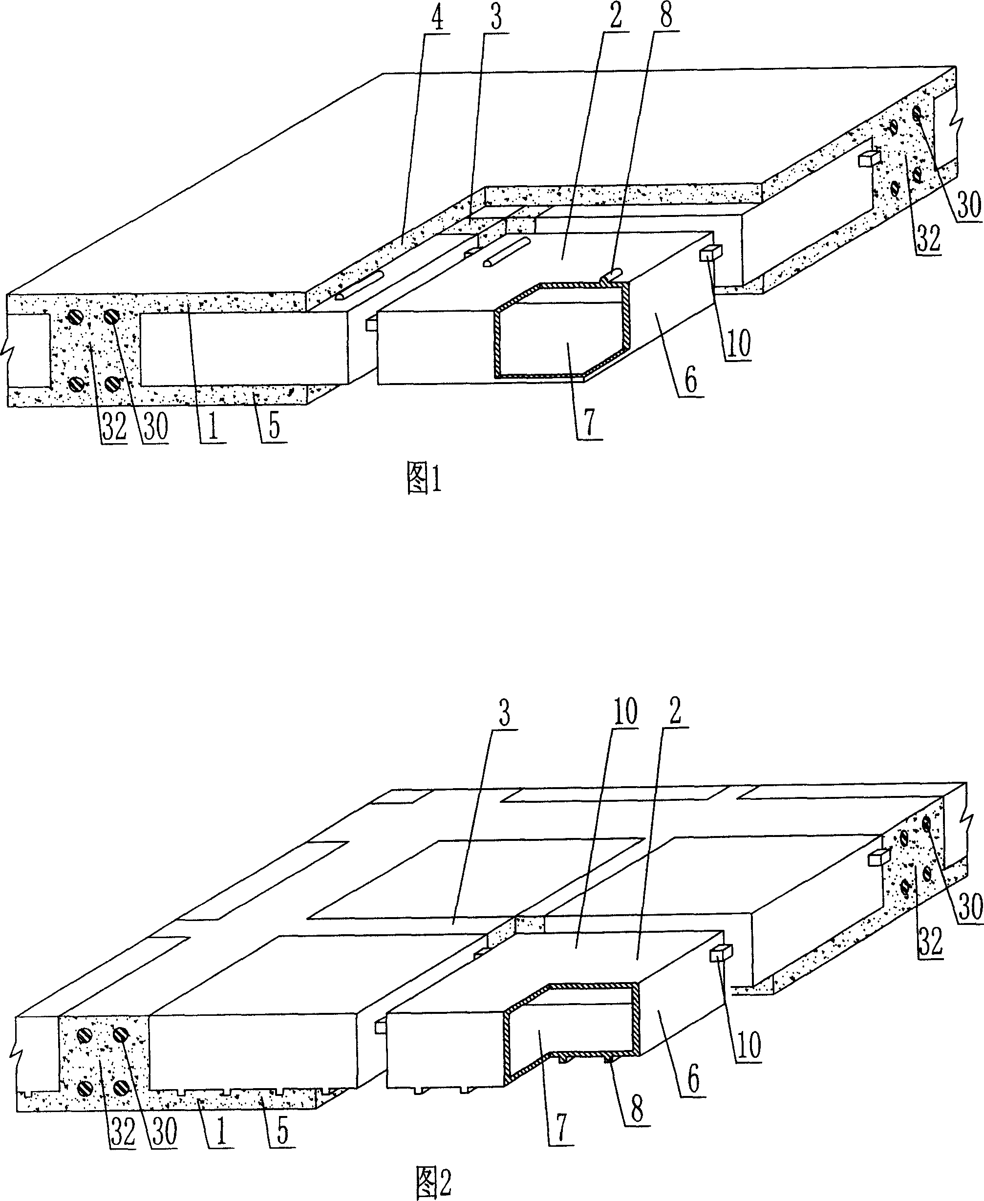
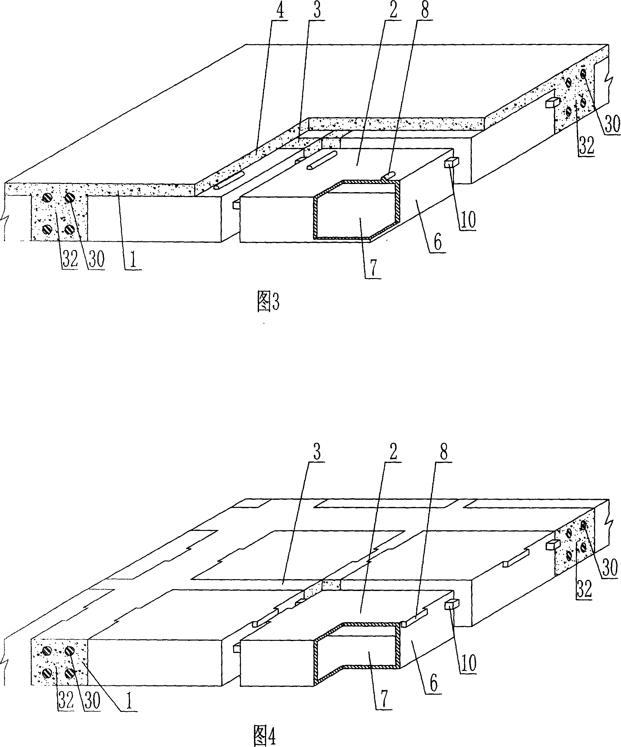
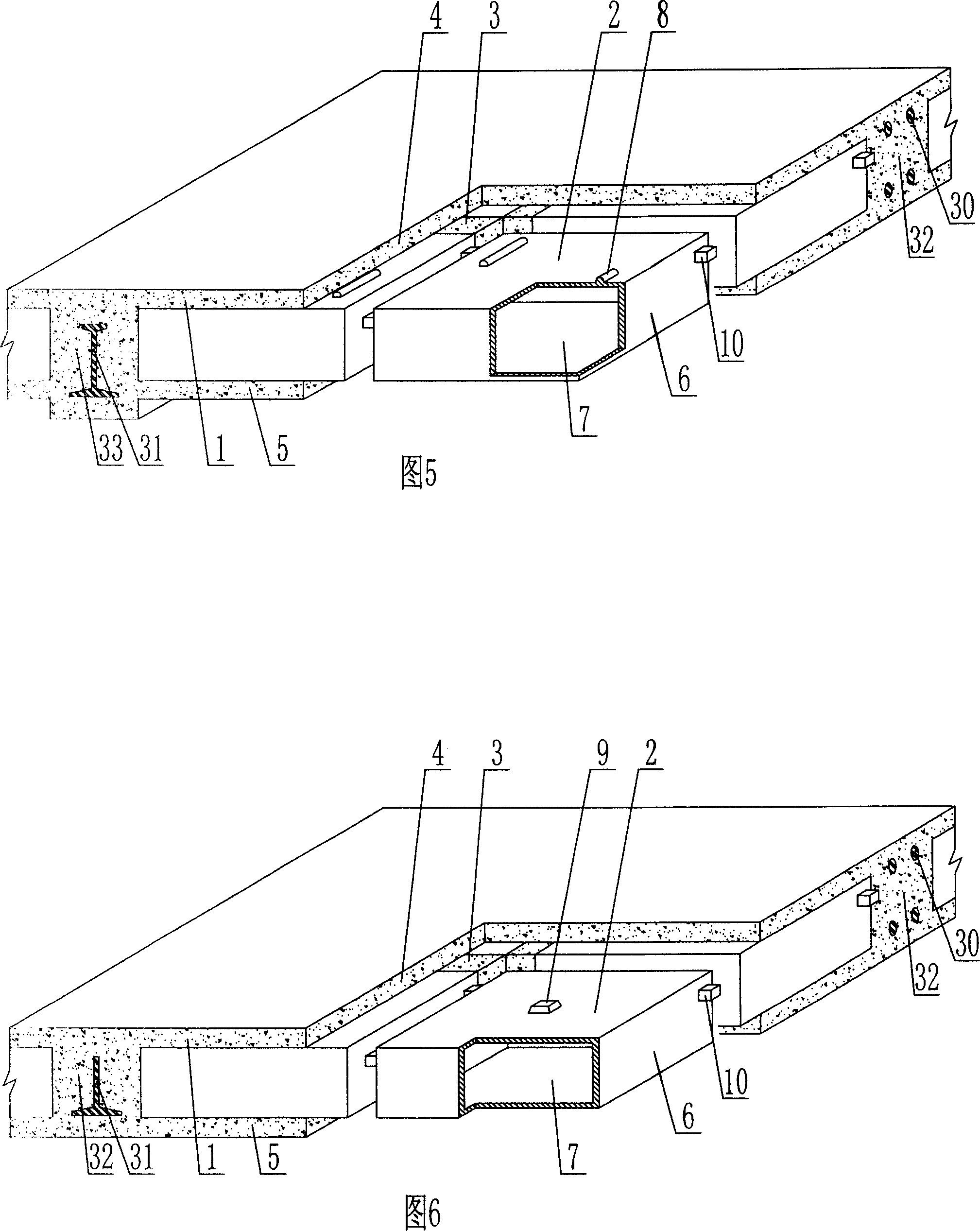
[0083] The present invention will be further described below in conjunction with the accompanying drawings and embodiments.

[0084] As shown in the accompanying drawings, the present invention comprises a reinforced concrete 1 and a hollow carcass 2, the hollow carcass 2 is wrapped in the reinforced concrete 1, the hollow carcass 2 are arranged alternately, and there are cast-in-situ reinforced concrete ribs 3 between them. It is an upper plate 4 of cast-in-place reinforced concrete, under which is a lower plate 5 of cast-in-place reinforced concrete, and the outer wall 6 encloses a hollow carcass 2 with a cavity 7, which is characterized in that the hollow carcass 2 is provided with steel bars The spacer 8 or / and spacer 9, and the side outer wall 6 of the hollow carcass 2 are provided with a rib spacing width limiting member 10. In each attached drawing, 1 is reinforced concrete, 2 is hollow carcass, 3 is cast-in-place reinforced concrete rib, 4 is upper plate of cast-in-place...


PUM


Abstract

The invention is a cast-in-site concrete hollow slab, comprising reinforced concrete, and hollow bodies, where the hollow bodies are wrapped in the reinforced concrete and alternate with cast-in-site reinforced concrete ribs, cast-in-site reinforced concrete top plate and infrabasal slab are on and under the hollow bodies respectively, the hollow body is formed by outer walls, and it is characterized in that: the hollow body is equipped with reinforcing bar packing strip or / and fill block, and the side outer wall of the hollow body is equipped with rib space width limiting piece. Thus, it can effectively prevent reinforcing bars rusting; besides, the rib space width limiting piece can effectively assure the width of hidden rib in building cover consistent with the designed width; and it is applied to cast-in-site reinforced concrete or prestressed reinforced concrete hollow building covers, roofs, wall bodies, foundation soleplates and hollow bridges, especially hollow, beam-free building covers.

Description

(1) Technical field [0001] The invention relates to a cast-in-place concrete hollow slab. (2) Background technology [0002] At present, the cast-in-place concrete hollow floor is a widely used floor structure. The lightweight permanent tire molds filled in it include various hollow tubes and boxes, and the boxes are hollow or solid. For example, the patent No. ZL99249798.1, which the applicant applied for on November 29, 1999, is a utility model patent named "fiber-reinforced thin-walled member for reinforced concrete filling", which discloses a thin-walled formwork member, including an upper plate, The surrounding side walls, the lower bottom, and the upper plate, the surrounding side walls and the lower bottom form a polyhedral cavity. Another example is that the patent No. is ZL00203695.9, and the name is called "combined concrete hidden rib floor slab" utility model patent, which discloses a formwork member in its specification, which can be solid or hollow, and its sh...

Claims


Application Information

Patent Timeline
Patent Type & Authority Applications(China)
IPC IPC(8): E04B5/18E04B5/36
Inventor 邱则有
Owner 湖南邱则有专利战略策划有限公司
Why Eureka
Try Eureka