Supercharge Your Innovation With Domain-Expert AI Agents!

Roller screw

A technology of rollers and leadscrews, applied in the direction of belts/chains/gears, mechanical equipment, transmissions, etc., can solve problems such as difficulties and achieve the effect of preventing interference

Active Publication Date: 2007-09-12
THK CO LTD
View PDF1 Cites 0 Cited by
  • Summary
  • Abstract
  • Description
  • Claims
  • Application Information

AI Technical Summary

Problems solved by technology

However, when the reed becomes larger, or the radius of curvature of the arc part of the return pipe becomes larger, while forming the rolling groove of the roller of the threaded sleeve (the return pipe installation groove does not interfere with the rolling groove of the roller), on the threaded sleeve Difficulty designing slots for mounting return pipes

Method used


Image

  • Roller screw
  • Roller screw
  • Roller screw

Examples


Embodiment Construction

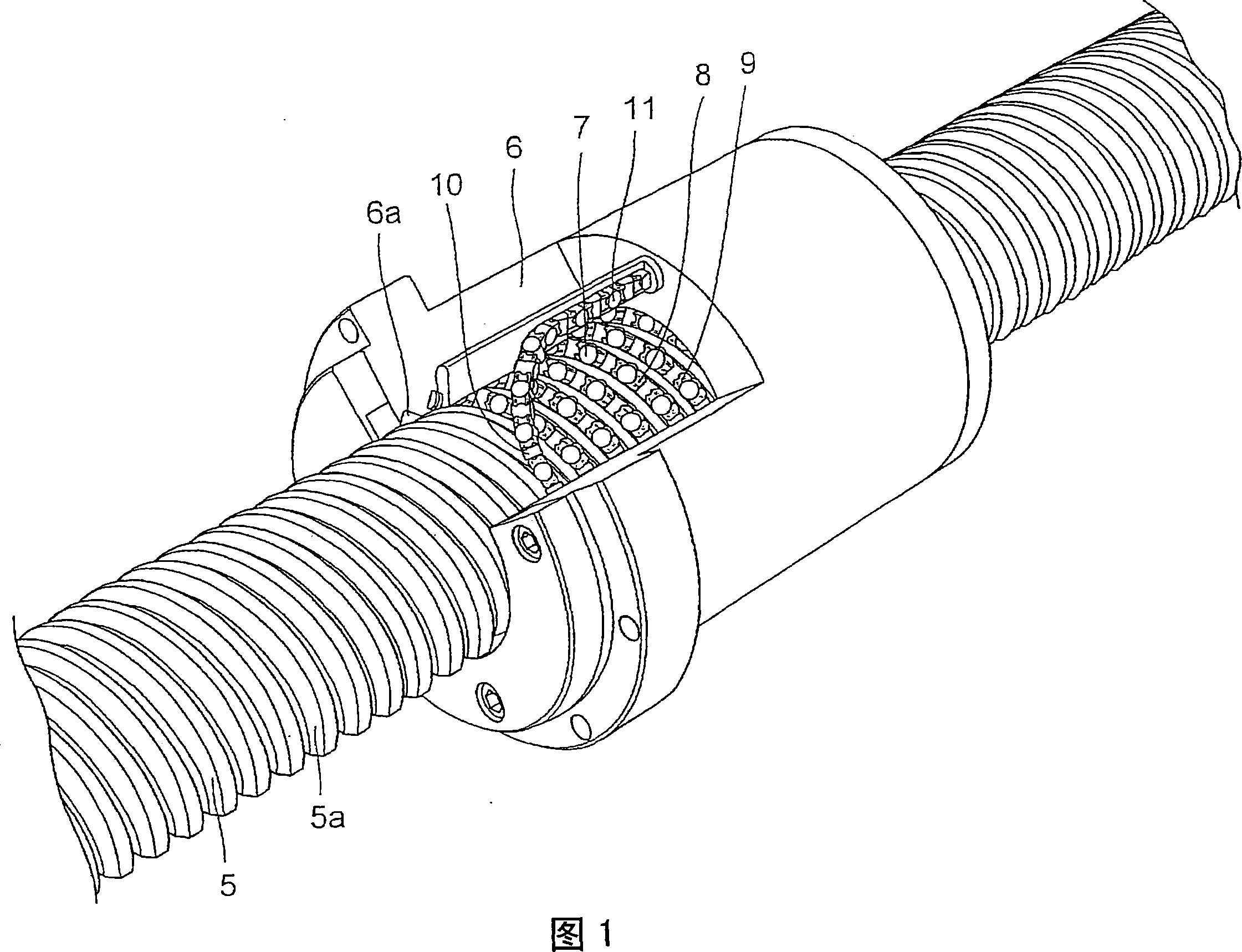
[0044] FIG. 1 is a perspective view showing a roller screw in one embodiment of the present invention. The roller screw includes: a screw shaft 5 having a helical roller groove 5a formed on the outer peripheral surface; and a helical roller groove 6a formed on the inner peripheral surface opposite to the roller groove 5a. Screw sleeve 6. Between the roller rolling groove 5a and the roller rolling groove 6a of the screw shaft 5, a plurality of rollers 7 are arranged crosswise so that the axes of adjacent rollers 7 are perpendicular to each other. A fixer 8 is interposed between the rollers 7 to prevent the rollers 7 from contacting each other.

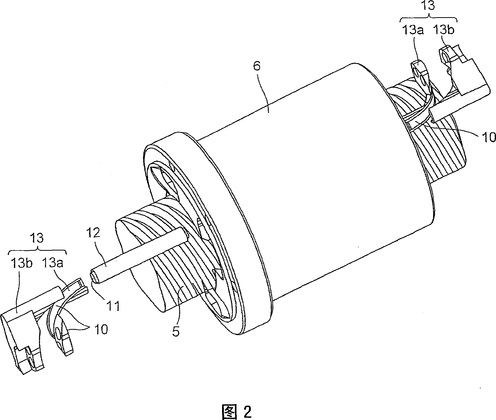
[0045] When the nut 6 is rotated relative to the screw shaft 5, the plurality of rollers 7 roll along the roller rolling groove 5a and the load roller raceway 9 between the roller rolling grooves 6a and simultaneously move. The roller rolled to one end of the load roller raceway 9 is lifted by the direction changing raceway 10 and ret...


PUM


Abstract

A roller screw having a structure suitable for circulating rollers. The roller screw has a screw shaft (5) in the outer peripheral surface of which a spiral roller rolling groove (5a) is formed, a nut (6) in the inner peripheral surface of which a spiral roller rolling groove (6a) facing the roller rolling groove (5a) of the screw shaft (5) is formed, and rollers (7) arranged in a load roller rolling path (9) between the roller rolling groove (5a) of the screw shaft (5) and the roller rolling groove (6a) of the nut (6). Inside the nut (6) is provided a roller return path (11) extended straight in parallel to the axis of the nut (6). Direction change-over path forming members (13) are attached to both end surfaces in the axial direction of the nut (6), and direction change-over path forming members (13) form direction change-over paths (10) that connect the load roller rolling path (9) and the roller return path (11). The roller return path (11) is twisted so that the attitude of the rollers (7) is rotated while they move in the roller return path (11).

Description

technical field [0001] The invention relates to a roller lead screw in which a roller can be rotated and moved between a screw shaft and a screw sleeve. Background technique [0002] A ball screw with a ball interposed between the screw shaft and the nut that enables rolling motion can reduce the friction coefficient when the screw shaft rotates with respect to the nut compared to a screw in sliding contact. Therefore, it is actually used in machine tools. Positioning mechanism, supply mechanism, or steering device of automobile, etc. [0003] In recent years, in order to increase the allowable load, a roller screw using rollers as rolling elements instead of balls as described in Patent Document 1 has been devised. In this roller screw, the circulation of the roller is the return pipe. The roller rolling in the roller groove of the screw shaft is lifted through the return pipe, and the roller returns to the original position through the return pipe to move infinitely. Th...

Claims


Application Information

Patent Timeline
Patent Type & Authority Applications(China)
IPC IPC(8): F16H25/22
CPCY10T74/19772F16H25/2247Y10T74/19767Y10T74/19749F16H2025/2271F16H25/2214Y10T74/19744F16H25/22
Inventor 寺町彰博道冈英一丹羽宏吉田明正
Owner THK CO LTD
Features
  • R&D
  • Intellectual Property
  • Life Sciences
  • Materials
  • Tech Scout
  • Unparalleled Data Quality
  • Higher Quality Content
  • 60% Fewer Hallucinations
Learn More