Automatic spring camera head

An automatic pop-up, camera technology, applied in the field of cameras, can solve the problems of easy wear and tear, affecting the life of the camera, etc.

Inactive Publication Date: 2007-10-03
LG ELECTRONICS (CHINA) R&D CENT CO LTD
View PDF0 Cites 26 Cited by
  • Summary
  • Abstract
  • Description
  • Claims
  • Application Information

AI Technical Summary

Problems solved by technology

[0002] In the past, in the technology of any mobile communication terminal such as a bar machine, a clamshell machine, and a slide machine, the camera is designed as a whole, and the mirror surface is exposed, which is easy to wear and tear, which affects the use effect and the life of the camera.

Method used


Image

  • Automatic spring camera head
  • Automatic spring camera head
  • Automatic spring camera head

Examples


Embodiment Construction

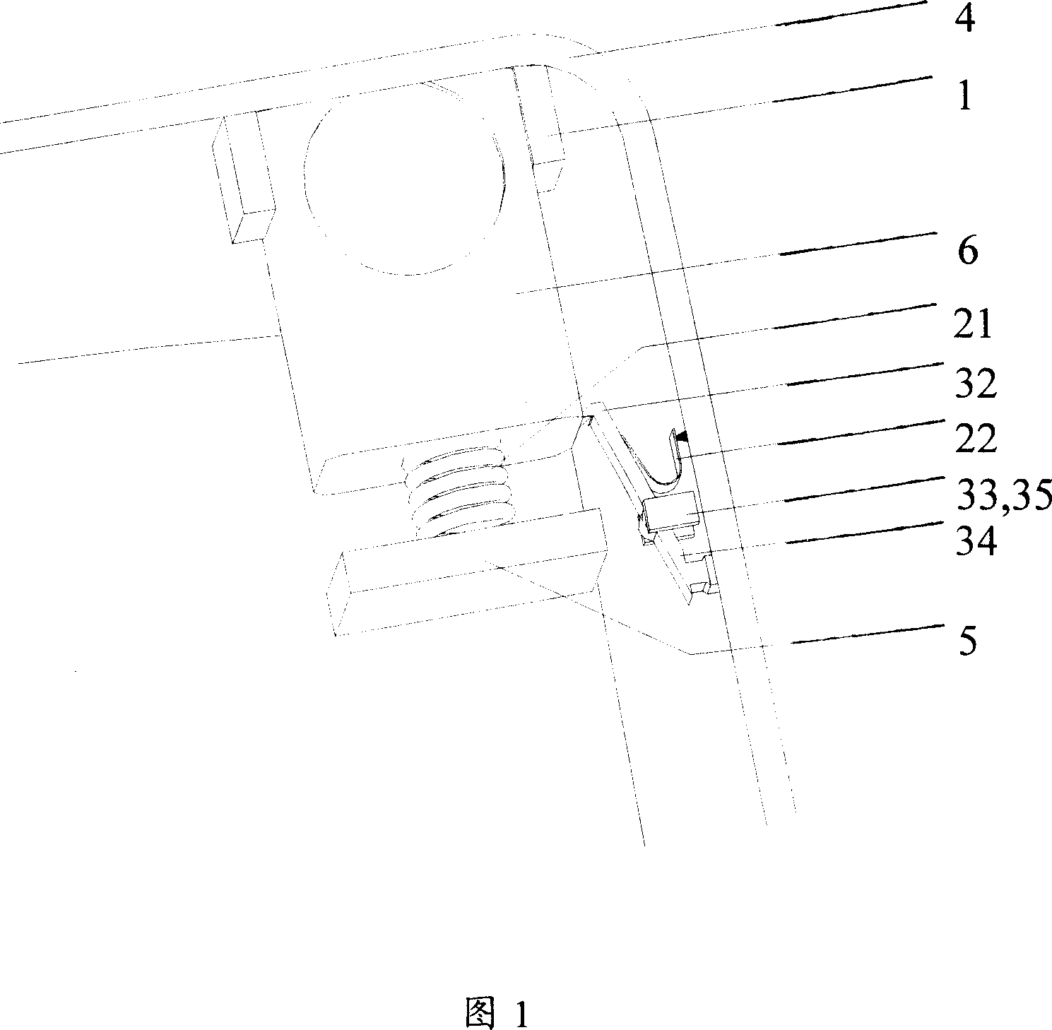
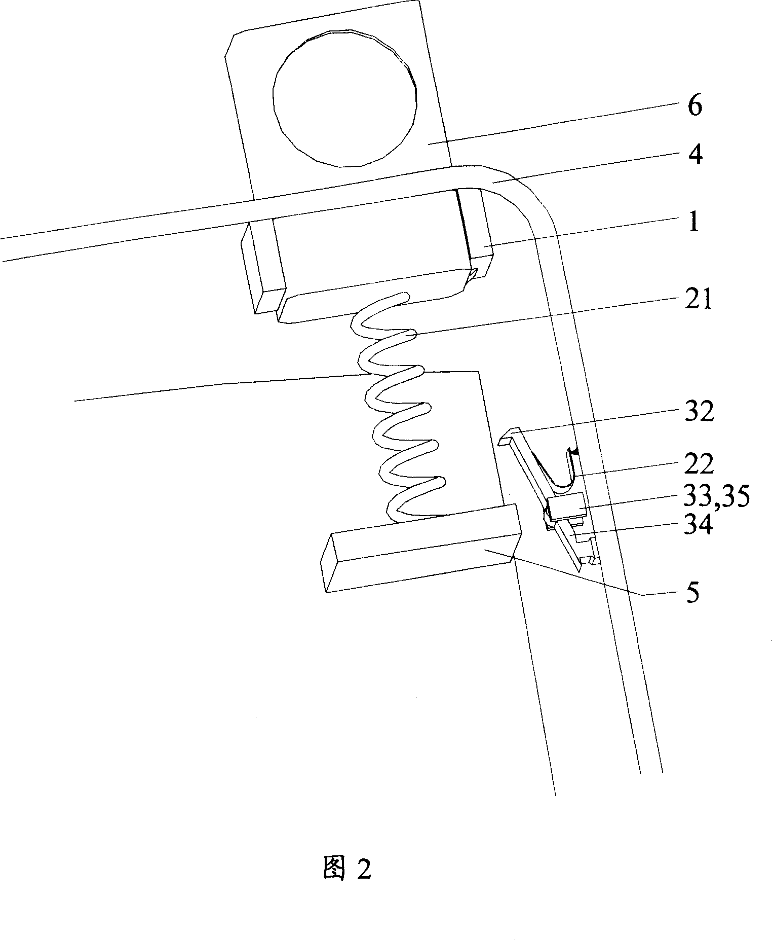
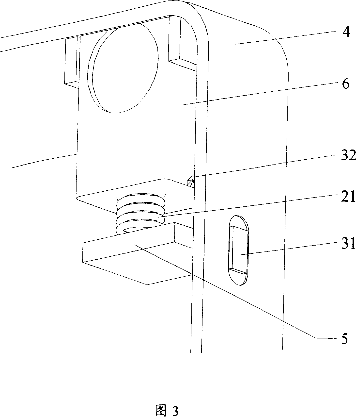
[0015] Please see Figure 1.

[0016] 1 is guide rails, which are two parallel pieces, and the front ends are respectively connected to the body 4; 6 is the camera, which is located in the protective cavity in the middle of the guide rail 1, and can be ejected or pressed in from the window on the upper side of the body 4; 5 is the lower end gear The board is fixed on the bottom surface of the fuselage 4, the spring 21 is connected between the bottom of the camera 6 and the lower end baffle plate 5, the camera 6 can be ejected from the window of the fuselage 4, and the trigger key spring 22 is fixed on the fuselage 4 On the side, the button 31 protrudes from the side of the fuselage 4 outside the side of the fuselage 4, and the trigger switch 32 is composed of a sloped step fixed on the side of the camera 6 and an oblique hook on the trigger key 3. The connecting rod The two ends of 34 are respectively connected button 31 and trigger switch 32, and connecting rod 34 is also rota...


PUM


Abstract

This invention relates to a camera head of a mobile communication terminal characterizing that the camera head includes: two parallel guideways fixed on a mobile communication terminal, a camera head held in a protection cavity formed by the guideways and jumping out from the terminal, a spring set at the bottom of the head and fixed on the bottom baffle and a trigger key mounted on the side of the terminal, in which, a key projecting over the side of the terminal on the trigger key is pressed to open the trigger switches on a connecting rod and the side of the head by a connecting rod unit acted by the other spring under the key and placed at the side of the terminal to spring the head up the side of the unit , when fixing, the head is pressed and locked by the trigger key due to the relative movement on the two slants on the trigger switches to protect the head when it is not used.

Description

technical field [0001] The invention relates to the field of cameras of mobile communication terminals. Background technique [0002] In the past, in the technology of any mobile communication terminal such as bar, clamshell, and slider, the camera is designed as a whole, and the mirror surface is exposed, which is easy to wear and tear, which affects the use effect and the life of the camera. Contents of the invention [0003] The purpose of the present invention is to provide an automatic pop-up camera to protect the camera lens from wear and tear, and at the same time, make the product appear more novel and easy to use. [0004] The present invention is characterized in that the automatic pop-up camera contains: [0005] Two parallel guide rails 1, the front end is connected with the fuselage 4; [0006] The camera 6 is accommodated in the protective cavity between the two parallel guide rails 1, and at the position of the fuselage 4 corresponding to the protective ca...

Claims


Application Information

Patent Timeline
Patent Type & Authority Applications(China)
IPC IPC(8): H04N5/225H04N5/247
Inventor 王萌
Owner LG ELECTRONICS (CHINA) R&D CENT CO LTD
Why Eureka
Try Eureka