Microphone pin and method for connection it with printed circuit board

A printed circuit board and microphone technology, which is applied in the direction of microphone mouth/microphone accessories, etc., can solve the problems of conductive layer damage, poor contact, conductive layer falling off, etc.

Inactive Publication Date: 2007-10-03
赵年东
View PDF0 Cites 2 Cited by
  • Summary
  • Abstract
  • Description
  • Claims
  • Application Information

AI Technical Summary

Problems solved by technology

The disadvantage of this kind of pin is that because of the interference fit between the pin and the reserved hole of the printed circuit board, when the pin is pressed into the hole of the printed circuit board, it is easy to press the corresponding hole on the printed ...

Method used


Image

  • Microphone pin and method for connection it with printed circuit board
  • Microphone pin and method for connection it with printed circuit board
  • Microphone pin and method for connection it with printed circuit board

Examples


Embodiment Construction

[0013] The present invention will be described in further detail below in conjunction with the accompanying drawings and embodiments.

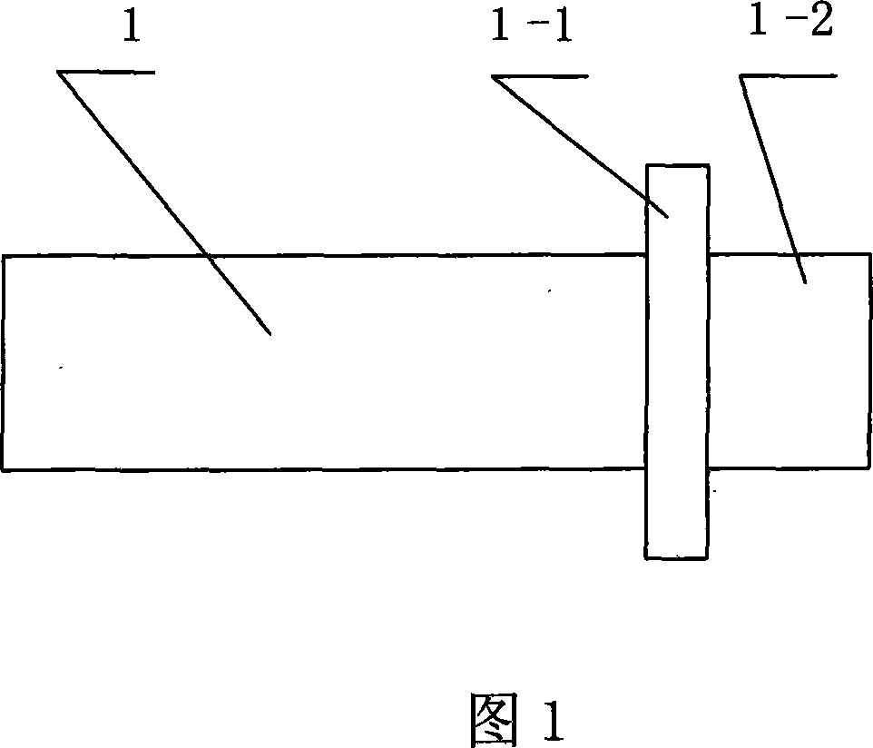
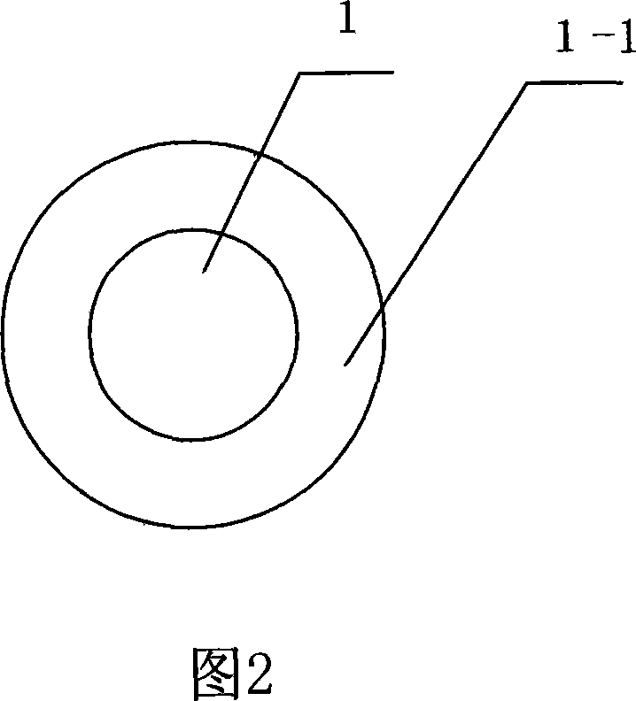
[0014] As shown in Figures 1 and 2, a microphone pin includes a pin body 1. The front part of the pin body 1 is a connection area 1-2 that matches the jack of the printed circuit board. The region of the connecting region 1-2 has a shoulder 1-1. The shoulder 1-1 can be single-layer or double-layer.

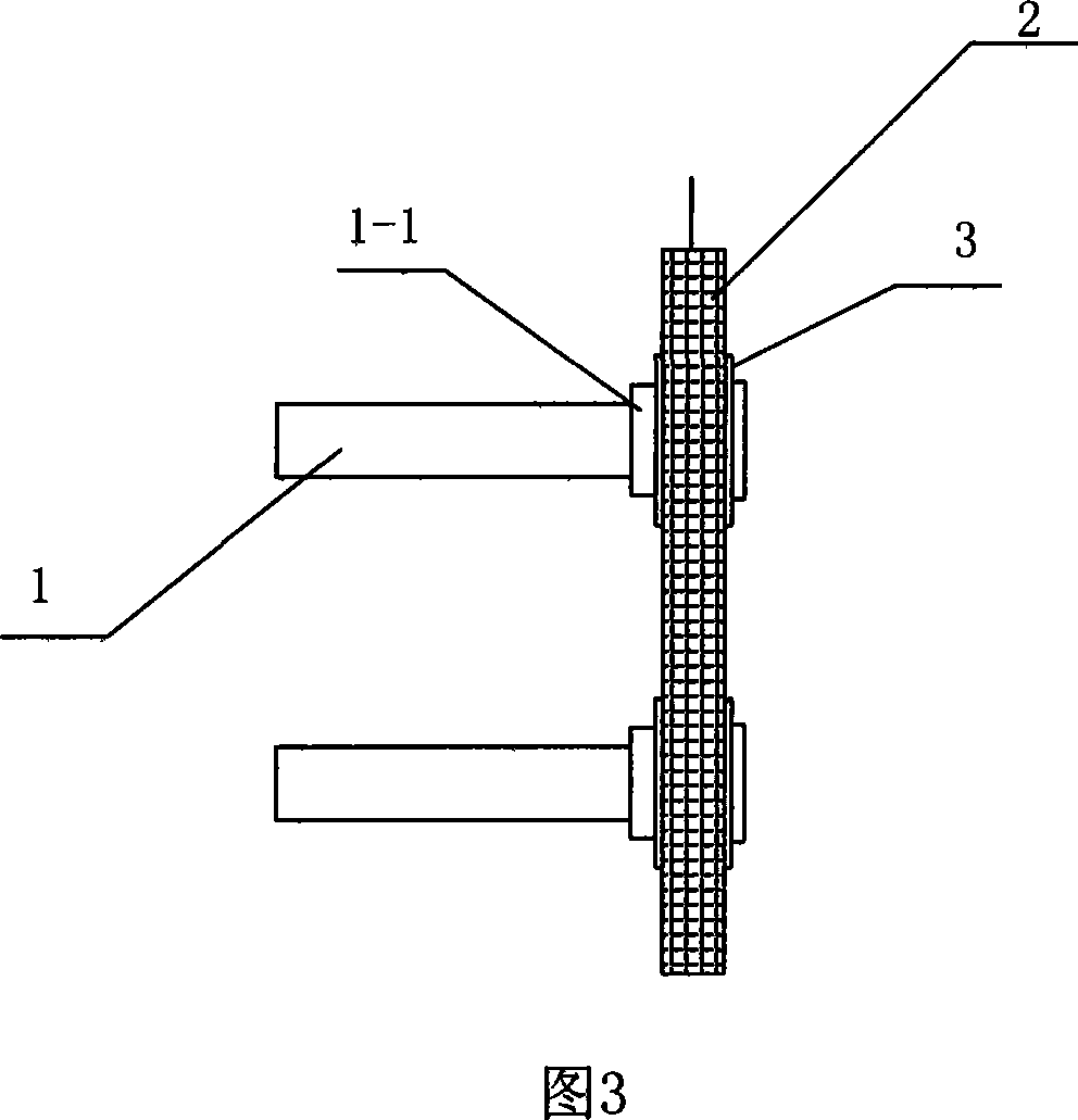
[0015] As shown in Figures 3, 4, and 5, a method for connecting a microphone pin to a printed circuit board, the steps are: first insert the front part 1-2 of the microphone pin into the reserved hole on the printed circuit board 2, and lead The feet are matched with the reserved holes, and the front ends of the pins are exposed from the reserved holes, and then the front ends of the pins are riveted with the printed circuit board by riveting. Since the pin fits with the reserved hole, the pin will not damage the conductive layer on the inner wa...


PUM


Abstract

The invention relates to a kind of pins of microphone, including a pin-body (1), a connectivity part (1-2) for connecting with the printed circuit board, a convex shoulder (1-1). The invention also provides a method for connecting the microphone pin and the printed circuit board shows as follow: It inserts the front-end of the microphone into the printed circuit board reserved pin-hole by transition fit, and exposes the front-end out of the reserved pin-hole, and then, it rivets the front-end with the printed circuit board through riveting.

Description

technical field [0001] The invention relates to a microphone pin for connection with a printed circuit board. The invention also relates to a connection method between the microphone pin and the printed circuit board. Background technique [0002] At present, the commonly used microphone pins are long and cylindrical. When this microphone pin is connected to the printed circuit board, its front end is pressed into the corresponding hole on the printed circuit board, and then the protruding end of the pin is connected to the printed circuit board. welding. The disadvantage of this kind of pin is that because of the interference fit between the pin and the reserved hole of the printed circuit board, when the pin is pressed into the hole of the printed circuit board, it is easy to press the corresponding hole on the printed circuit board and the inner wall of the hole. The conductive layer is damaged or even causes the conductive layer to fall off, which affects the reliabili...

Claims


Application Information

Patent Timeline
IPC IPC(8): H04R1/08
Inventor 赵年东
Owner 赵年东
Why Eureka
Try Eureka