System and method of testing humidity in a sealed mems device

A humidity, in-device technology, applied in measurement devices, microstructure devices, circuits, etc., to solve problems such as failure to recognize inspection or measurement of MEMS devices

Inactive Publication Date: 2007-10-10
IDC LLC
View PDF0 Cites 10 Cited by
  • Summary
  • Abstract
  • Description
  • Claims
  • Application Information

AI Technical Summary

Problems solved by technology

[0003] Additionally, there is no recognition in the prior art of the need to inspect or measure humidity (relative humidity) levels within a MEMS device after fabrication of the MEMS package is complete, in order to, for example, estimate the lifetime of the device or determine if the package is defective

Method used


Image

  • System and method of testing humidity in a sealed mems device
  • System and method of testing humidity in a sealed mems device
  • System and method of testing humidity in a sealed mems device

Examples


Embodiment Construction

[0040]The following detailed description is directed to certain specific embodiments of the invention. However, the invention can be implemented in many different ways. Throughout this description reference is made to the drawings in which all like parts are designated by like numerals. As will be appreciated from the following description, the embodiments may be implemented in any device configured to display images, whether in motion (eg, video) or stationary (eg, still images), and whether textual or pictorial. More specifically, it is contemplated that the described embodiments may be implemented in or associated with a variety of electronic devices such as, but not limited to, mobile phones, wireless devices, personal data assistants (PDAs) , hand-held or portable computers, GPS receivers / navigators, cameras, MP3 players, video cameras, game consoles, watches, clocks, calculators, television monitors, flat panel displays, computer monitors, automotive displays (e.g., mil...


PUM


Abstract

One embodiment provides a method of testing humidity, comprising: determining a property of a device which encloses a plurality of interferometric modulators; and determining a relative humidity value or a degree of the relative humidity inside the device based at least in part upon the determined property. In one embodiment, the property of the device includes one of the following: i) a weight of the device, ii) a color change of a desiccant enclosed in the device, iii) a resistance inside the device, iv) whether frost formed in an inside area of the device which is contacted by a cold finger device, v) whether a desiccant enclosed in the device, when water vapor is provided into the device, is working properly, and vi) combination of at lest two of i)-v).

Description

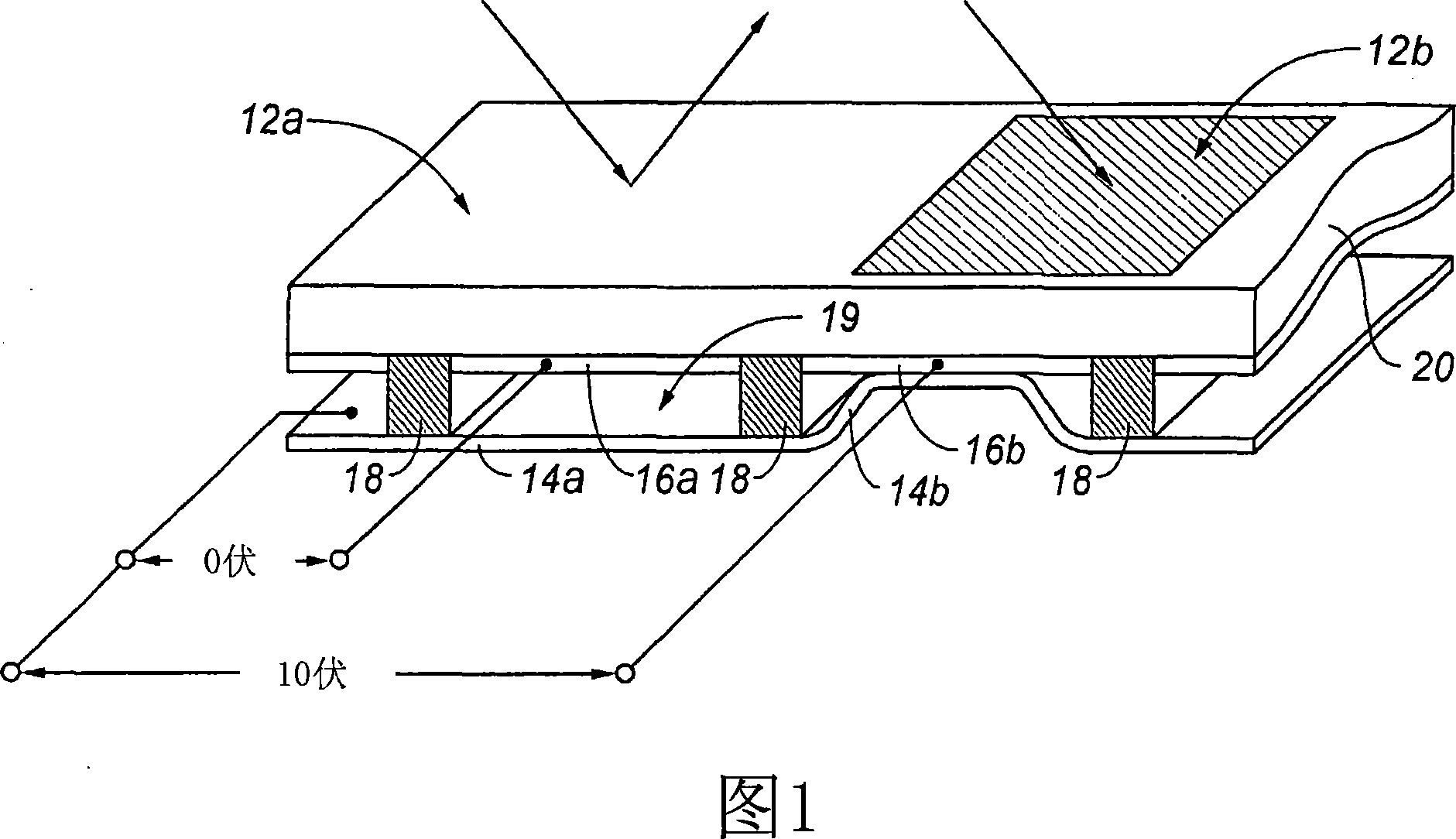
technical field [0001] The field of the invention relates to microelectromechanical systems (MEMS). Background technique [0002] Microelectromechanical systems (MEMS) contain micromechanical components, actuators, and electronics. Micromechanical elements may be created using deposition, etching, and / or other micromachining processes that etch away portions of substrates and / or deposited material layers or add layers to form electrical and electromechanical devices. One type of MEMS device is called an interferometric modulator. As used herein, the term interferometric modulator or interferometric light modulator refers to a device that selectively absorbs and / or reflects light using the principles of optical interference. In some embodiments, an interferometric modulator may include a pair of conductive plates, one or both of which may be transparent and / or reflective in whole or in part, and capable of relative motion upon application of an appropriate electrical signal...

Claims


Application Information

Patent Timeline
Patent Type & Authority Applications(China)
IPC IPC(8): G01M3/02B81B7/00
Inventor 布莱恩·J·加利洛朗·帕尔玛蒂尔马尼什·科塔里威廉·J·卡明斯
Owner IDC LLC
Why Eureka
Try Eureka