Wall brushing device

A technology for wall painting and painting, which is applied in the direction of machines/engines, liquid variable capacity machinery, pumps with flexible working elements, etc. Influence and other issues, to avoid frequent opening and closing

Inactive Publication Date: 2007-10-24
ZHEJIANG UNIV OF TECH
View PDF1 Cites 3 Cited by
  • Summary
  • Abstract
  • Description
  • Claims
  • Application Information

AI Technical Summary

Problems solved by technology

It can be seen that during the operation of the equipment, the motor will be turned on and off more frequently, which will have adverse effects on the motor itself and the power grid.
In addition, at the moment when the motor is turned on and off, the flow rate at the paint output end is prone to sudden changes, which also has a great impact on the stability of the paint brushing work.

Method used


Image

  • Wall brushing device
  • Wall brushing device

Examples


Embodiment 1

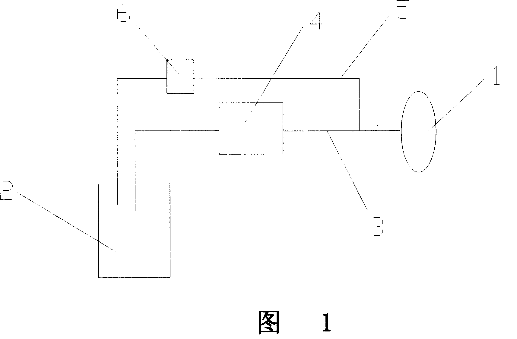
[0019] With reference to Fig. 1, 2, a kind of wall brushing device comprises brushing roller 1, and one end communicates with paint storage cylinder 2, and the other end connects paint conveying pipeline 3 of brushing roller 2, installs on described paint conveying pipeline 3 There is a diaphragm pump 4 and its driving motor, and also includes a return line 5 connected to the paint storage tank 2 at one end and connected to the paint delivery line behind the output end of the diaphragm pump 4 at the other end. A regulating valve 6 is also installed on the return line 5 ;

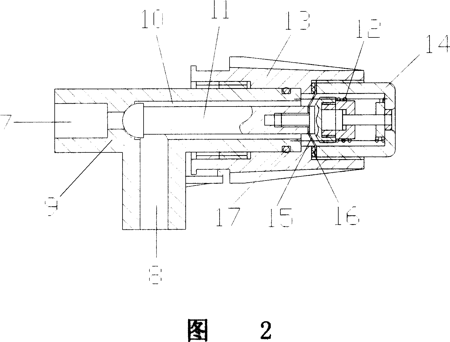
[0020] The regulating valve includes a valve body 9 having a liquid inlet 7 and a liquid outlet 8, and the valve body 9 also has a valve chamber 10 communicating with the liquid inlet 7 and the liquid outlet 8, and the valve chamber 10 There is a spool 11 inside. When the front end of the spool 11 touches the connection between the liquid inlet 7 and the valve cavity 10, a sealing surface is formed at the ab...

Embodiment 2

[0024] The valve body 9 of the regulating valve is also threaded to a knob sleeve 13, the end of the valve body 9 is equipped with a rear end cover 14, and the rear end cover 14 is affixed to the knob sleeve 13, and the pre-tightened The spring 12 connects the valve core 11 and the rear end cover 14 . A sealing gasket 15 and a diaphragm 16 are installed between the rear end cover 14 and the knob cover 13, a sealing ring 17 is arranged between the knob cover 13 and the valve body 9, and the sealing gasket 15, the diaphragm 16 and the sealing ring 17 Can prevent the leakage of paint.

[0025] Manually adjust the knob sleeve 13 so that the valve core 11 no longer seals the liquid inlet 7 and the valve chamber 10 of the valve body, so that the paint flows back to the liquid storage cylinder 2 through the liquid inlet, the valve chamber and the liquid outlet, that is, the infusion The paint to the brush roller can be diverted to regulate the flow of paint to the brush roller.

[...


PUM


Abstract

A wall-brushing device includes spread coating cylinder, coating transfer pipelines which one end is connected with paints-storing tubular and another end is connected with spread coating cylinder, the coating transfer pipelines are equipped with bellows pump and its driving motor, and it also includes inverse flow pipelines which one end is connected with coating transfer pipelines and another end is connected with paints-storing tubular, the inverse flow pipelines are equipped with governing valve; the governing valve includes valves of liquid inlet mouth and liquid outlet mouth, the valve body also includes valve cavity connecting liquid inlet mouth and liquid outlet mouth, the valve cavity is equipped with spools which controls liquid inlet mouth and liquid outlet mouth and is conducted with valve cavity, the front end of the spool is conflicted with the connecting position of liquid inlet mouth and valve cavity, the contact position forms sealing face, the end is connected with the rear end of valve through preloading spring. The beneficial effects of the invention are: 1. the motor and the transportation pump operate continuously and so the frequent start and stop are avoided. 2. The practical and new device realizes limiting maximum discharge pressure and adjusting the paints flow transferred into spread coating cylinder simultaneously.

Description

(1) Technical field [0001] The invention relates to a wall brushing device. (2) Background technology [0002] The wall brush is used in paint painting occasions, and is used to automatically transport the paint from the paint storage cylinder to the brush roller to realize continuous brush painting. [0003] The U.S. patent No. US5096392 provides a kind of paint delivery equipment, which is equipped with a brushing roller to become a wall brush, which includes a paint delivery pipeline and a diaphragm pump installed on the paint delivery pipeline. A pressure-sensing diaphragm for sensing the conveying pressure and a micro switch for accepting the deformation of the pressure-sensing diaphragm are also installed on the conveying pipeline. In order to prevent the motor from operating under excessive load, it is necessary to specify the maximum delivery pressure of a pipeline. When the pressure acting on the pressure-sensitive diaphragm reaches the maximum delivery pressure, t...

Claims


Application Information

Patent Timeline
Patent Type & Authority Applications(China)
IPC IPC(8): E04F21/06F04B43/02
Inventor 翁泽宇
Owner ZHEJIANG UNIV OF TECH
Why Eureka
Try Eureka