
Kinetic-energy expanded converter

A technology of converters and kinetic energy, which is applied in transmission devices, fluid transmission devices, belts/chains/gears, etc., and can solve problems such as the destruction of the earth's environment, air or noise pollution, etc.

Inactive Publication Date: 2007-11-21
陈 仁性
View PDF0 Cites 2 Cited by
  • Summary
  • Abstract
  • Description
  • Claims
  • Application Information

AI Technical Summary

Problems solved by technology

[0002] The general power is to use the motor or engine to generate kinetic energy, which becomes linear power or rotational power for use, which includes converting into air pressure or oil pressure for power use, but whether the power is generated by the engine or motor, most of the methods are external The kinetic energy that enters is converted into motion power from the inside to the outside. It is inevitable to consume a lot of fuel or power resources to generate low-torque power, and its power generation will also create a lot of air or noise pollution, which will have an invisible impact on the earth's environment. direct or indirect damage

Method used


Image

  • Kinetic-energy expanded converter
  • Kinetic-energy expanded converter
  • Kinetic-energy expanded converter

Examples


Embodiment Construction

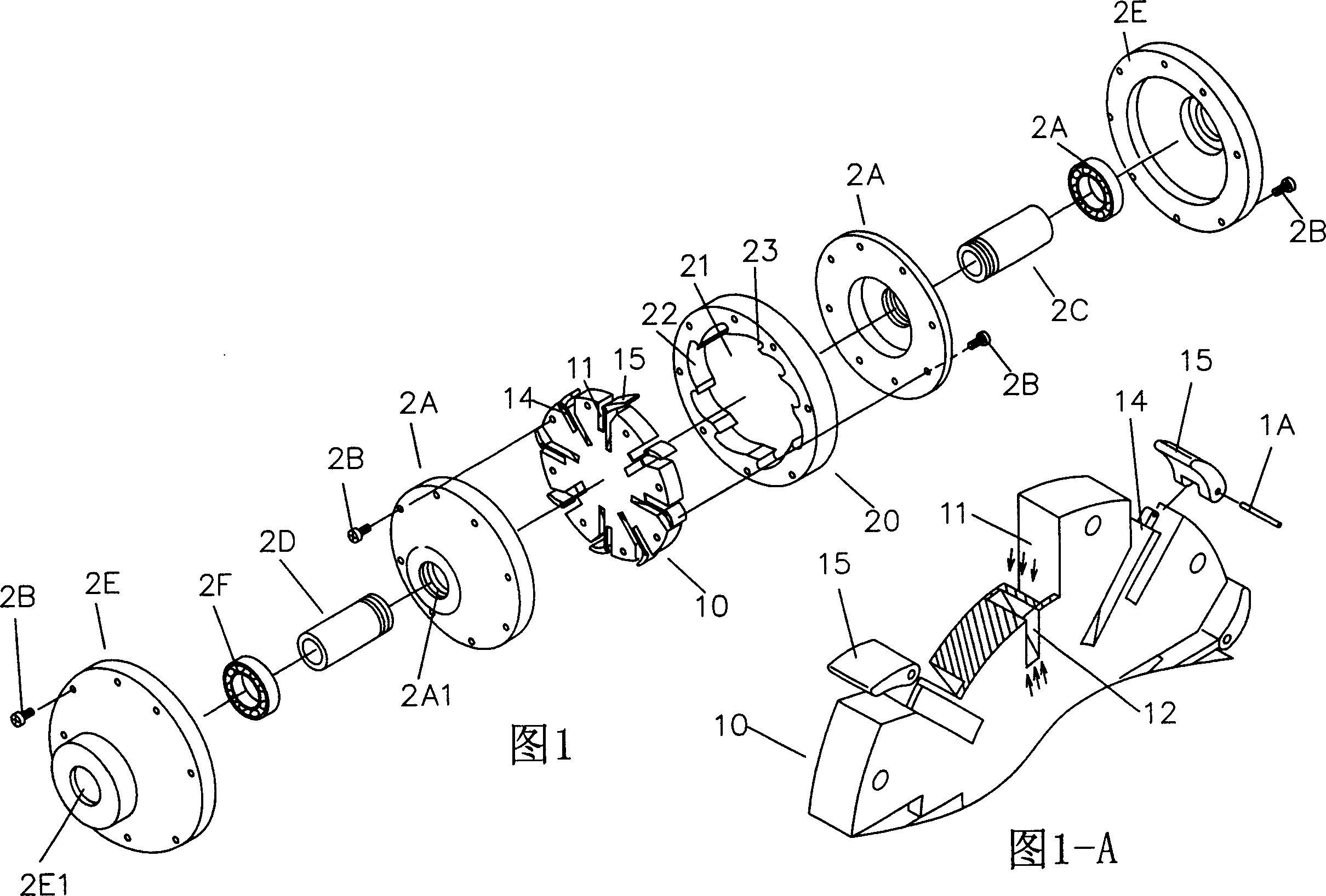
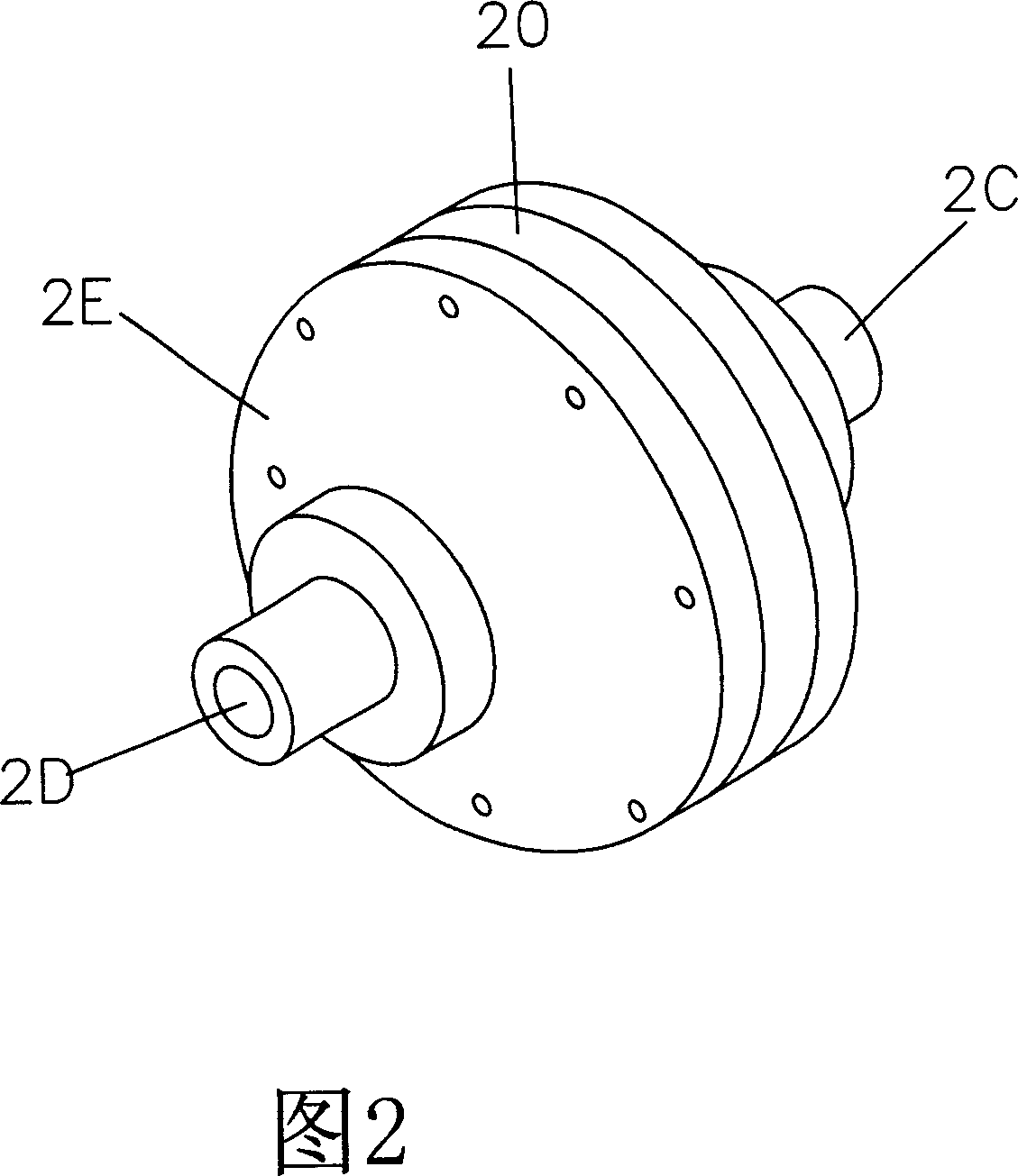
[0022] Referring to Fig. 1, Fig. 1-A, Fig. 2, Fig. 3-A and Fig. 3-B, a kind of kinetic energy expansion converter of the present invention comprises; inner disk (also known as distribution disk, fixed) 10, set on an outer disk (also known as force plate, rotatable) 20, which is in the shape of a disc, which can distribute the fluid into several or dozens (set the number of outlets according to the size of the circumference) with the same pressure, and distribute them equally on the periphery of the inner disc 10 Circumferential outlet, so that the fluid with pressure pushes the outer plate 20 (forced plate) at the same time, and the outer edge 13 of the inner plate 10 is sequentially arranged with a number of oil guide grooves 11 and return grooves 12. There is a return flow between the oil guide groove 11 and the return groove 12 The holes communicate with each other, and a groove bar 14 protrudes from the inner space of each oil guide groove 11, and an arc-shaped block 15 is ...


PUM


Abstract

The invention is a kind of kinetic energy to expand converters, will be pressurized fluid after importation of this device to form circular movement principle of the lever arm and the physical characteristics of a kinetic energy, the Greek configuration to the appropriate physical characteristics of this invention to be brought into fuller play to make energy conservation and energy will lead to expansion of mechanical energy devices.

Description

technical field [0001] The invention relates to a kinetic energy conversion mechanism, in particular to a kinetic energy expansion converter structure. Background technique [0002] The general power is to use the motor or engine to generate kinetic energy, which becomes linear power or rotational power for use, which includes converting into air pressure or oil pressure for power use, but whether the power is generated by the engine or motor, most of the methods are external The kinetic energy that enters is converted into motion power from the inside to the outside. It is inevitable to consume a lot of fuel or power resources to generate low-torque power, and its power generation will also create a lot of air or noise pollution, which will have an invisible impact on the earth's environment. direct or indirect damage. [0003] Therefore, how to eliminate the above-mentioned deficiencies is the technical difficulty that the applicant in this case wants to solve. [0004] ...

Claims


Application Information

Patent Timeline
Patent Type & Authority Applications(China)
IPC IPC(8): F16H43/00
Inventor 陈仁性
Owner 陈 仁性
Learn More