Permanent magnet embedded rotor

a permanent magnet and rotor technology, applied in the direction of dynamo-electric machines, magnetic circuit rotating parts, magnetic circuit shape/form/construction, etc., can solve the problem of high manufacturing cost, achieve strong rotation torque, reduce manufacturing cost, and improve rotation efficiency

Active Publication Date: 2016-06-07
NISHIMURA HIROYUKI +1
View PDF40 Cites 0 Cited by
  • Summary
  • Abstract
  • Description
  • Claims
  • Application Information

AI Technical Summary

Benefits of technology

[0021]With the permanent magnet embedded rotor according to the first aspect of the present invention, by increasing the adsorption power of the rotating magnetic field, a strong rotation torque can be generated. Further, a large clearance can be secured between the stator and the rotor. Therefore, even when the rotor thermally expands due to high-speed rotation or long driving and, as a result, the clearance changes, a failure due to contact, etc., between the rotor and the stator hardly occurs. In addition, synchronism loss hardly occurs, so that the rotation efficiency is improved. Even when the rotor does not synchronize with the rotating magnetic field, a rotation torque can be generated and the rotating state can be maintained. Further, the manufacturing cost can be reduced. In addition, an eddy current loss is reduced and heat generation can be reduced.
[0022]With the pe

Problems solved by technology

H10-225032 noted above, magnets and spacers must be processed i

Method used


Image

  • Permanent magnet embedded rotor
  • Permanent magnet embedded rotor
  • Permanent magnet embedded rotor

Examples


example 1

[0031]A permanent magnet embedded rotor of Example 1 is described with reference to FIG. 1 to FIG. 4

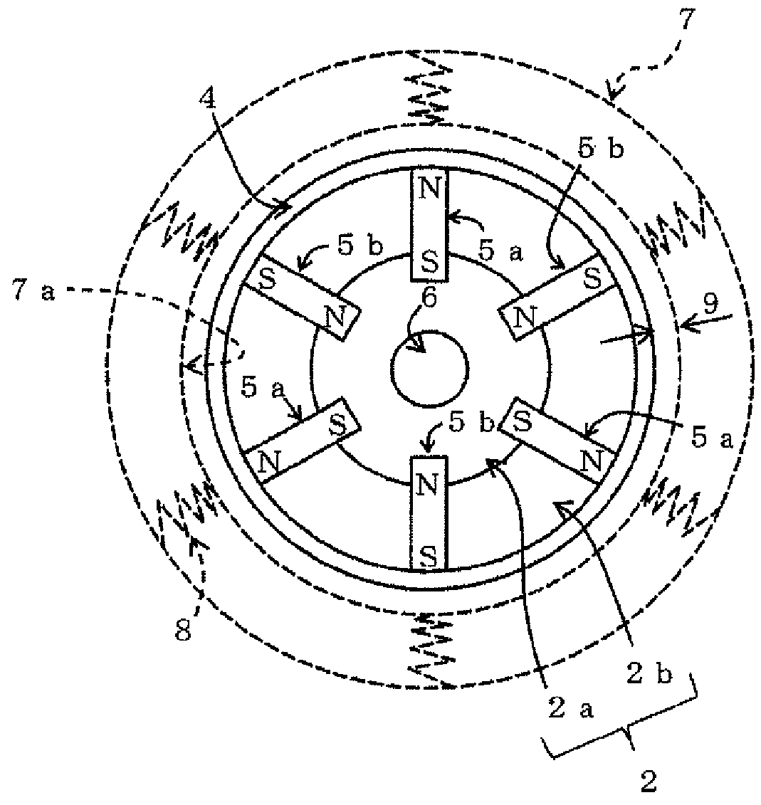
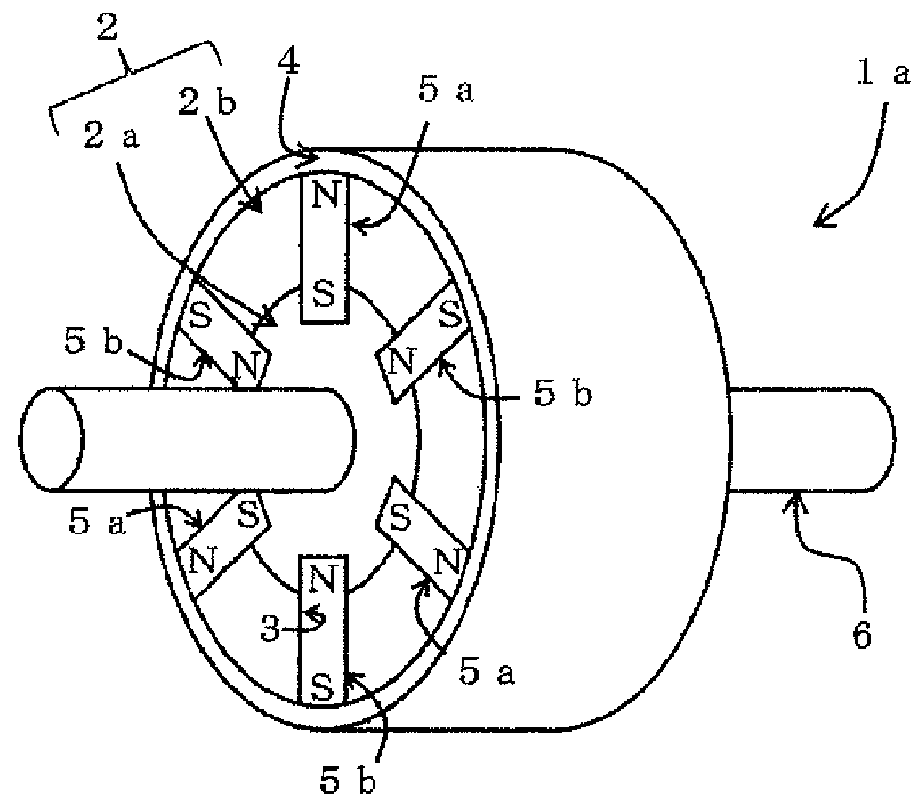
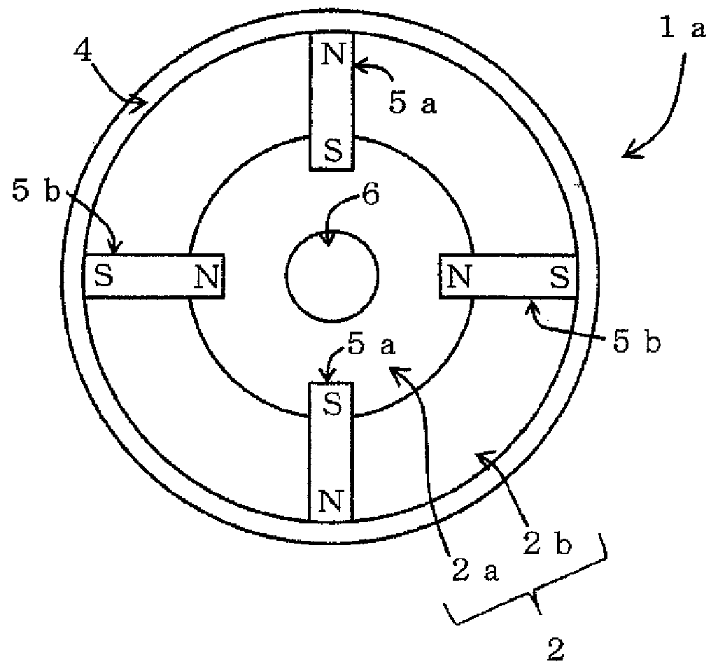
[0032]FIG. 1(a) and FIG. 1(b) are an external perspective view and a plan view of Example 1 of a permanent magnet embedded rotor according to an embodiment of the present invention. FIG. 2(a) and FIG. 2(b) are plan views showing the permanent magnet embedded rotor of the present example and a modification thereof. In FIG. 1(b), a stator is schematically shown by dashed lines.

[0033]As shown in FIG. 1(a), the permanent magnet embedded rotor (hereinafter, referred to as rotor 1a) of the present example includes a rotor core 2 on which an even number of insertion grooves 3 each being formed substantially in a narrow and long rectangular shape while an outer peripheral side thereof is slightly curved. The insertion groove includes two parallel planes running from the outer peripheral surface toward the rotation center in a plan view, a cylindrical body 4 that is made of a nonmagnetic metal...

example 2

[0041]A permanent magnet embedded rotor of Example 2 is described with reference to FIG. 5 (corresponding to, particularly, claim 5).

[0042]FIG. 5 is a plan view of a permanent magnet embedded rotor of Example 2. The components shown in FIG. 1 to FIG. 4 are provided with the same reference symbols and description thereof is omitted.

[0043]As shown in FIG. 5, the permanent magnet embedded rotor of the present example (hereinafter, referred to as rotor 1b) is structured so that, in the rotor 1a of Example 1, permanent magnets 5c each of which is rectangular in a plan view and has magnetic poles formed on both ends are embedded in the outer peripheral surface of the columnar body 2 so that the magnetic poles reverse to the magnetic poles on the sides in contact with the columnar body 2 of the permanent magnets 5a and 5b are made close to these magnetic poles of the permanent magnets, respectively. In the present example, the permanent magnets 5c are embedded in the outer peripheral surfa...


PUM


Abstract

A permanent magnet embedded rotor disposed coaxially with a cylindrical stator having a plurality of coils in the circumferential direction includes a rotor core that includes a columnar body made of a magnetic metal and a spacer made of a nonmagnetic material, and has an even number of insertion grooves, a cylindrical body that is made of a nonmagnetic metal with good electrical conductivity and externally inserted on the rotor core, permanent magnets embedded in the insertion grooves so that their N poles and S poles alternately come into contact with the inner peripheral surface of the cylindrical body, and a rotary shaft made of stainless steel fit into a rotation center of the rotor core.

Description

[0001]This application is a national stage of International Application No. PCT / JP2011 / 058236 filed Mar. 31, 2011, which claims the benefit of foreign filing based on Japanese Patent Application No. 2010-111429 filed May 13, 2010, the entire contents of which are incorporated herein by reference.TECHNICAL FIELD[0002]The present invention relates to a permanent magnet embedded rotor to be used in a rotary electric machine such as a motor and an electric generator, and specifically, to a permanent magnet embedded rotor to be used in a synchronous rotary electromotor that rotates a rotor by interaction of a rotating magnetic field generated by supplying an electric current to a stator and permanent magnets embedded in the rotor.BACKGROUND ART[0003]A basket-type induction motor is simple and strong, so that it is highly reliable and conventionally most commonly used in industry. However, in recent years, a synchronous motor using permanent magnets that has high efficiency and obtains hi...

Claims


Application Information

Patent Timeline
IPC IPC(8): H02K21/12H02K1/28H02K1/30H02K21/28H02K21/14H02K1/27
CPCH02K1/278H02K1/27H02K1/2753H02K1/28H02K1/30H02K21/12H02K21/14H02K21/28
Inventor NISHIMURA, MASASHI
Owner NISHIMURA HIROYUKI
Why Eureka
Try Eureka