Rotational force generating device using clock spring

a technology of rotational force and clock spring, which is applied in the direction of spring motors, machines/engines, motors, etc., can solve the problems of inability to adjust the rotation speed (revolutions per minute (rpm)) restrict the use of such a rotational force generating means, etc., to achieve strong output rotational force, fine adjustment of the rpm of the output shaft, and more deliciously cooked food

Active Publication Date: 2019-03-28
GREENIMT CO LTD
View PDF6 Cites 1 Cited by
  • Summary
  • Abstract
  • Description
  • Claims
  • Application Information

AI Technical Summary

Benefits of technology

[0030]As described above, according to the present invention, the RPM of the output shaft can be freely adjusted by a user. Therefore, when the present invention is applied to rotary food-roasting devices, the RPM of the output shaft can be adjusted according to the kind of food so as to prepare more deliciously cooked food. In addition, the present invention has an advantage of providing a rotational force generating device using a clock spring, the device being configured in such a manner that it is possible to prevent the output shaft thereof from rotating slowly or stopping due to weakening of the unwinding rotational force of the spiral spring in the second half period of the operation span of the output shaft. Therefore, a constant unwinding force can be transmitted to the output shaft during both the first half period and the second half period of the operation span. That is, the strong output rotational force can be maintained even during the second half period of the operation span.
[0031]In addition, according to the present invention, it is possible to finely adjust the RPM of the output shaft by finely adjusting the pressing force applied to the circumferential surface of the input shaft by rotating the adjustment bolt by a fine interval in the process of adjusting the RPM of the output shaft. Therefore, when the present invention is applied to rotary food-roasting devices, more delicious food can be prepared.
[0032]In addition, according to the present invention, the rotational force generating device using a clock spring includes the synthetic resin coating layer formed on the surface of the input shaft contact recess of the brake member constituting the output RPM adjusting means. Therefore, when the metallic input shaft is rotated while being in contact with the brake member, the coating layer reduces noise during the rotation of the input shaft.

Problems solved by technology

Therefore, the use of such a rotational force generating means is restricted in a situation where supply of electricity or fuel is difficult.
However, the conventional clock spring-based rotary force generator 100 has a problem that the rotation speed (revolutions per minute (RPM)) of the output shaft cannot be adjusted.
The clock spring-based rotary force generator 100 has another problem that, in the second half period of a full operation span of the output shaft, the unwinding rotational force decreases due to the inherent nature of a spiral spring and thus the rotational force of the output shaft decreases, resulting in the output shaft rotating slowly or even stopping.

Method used


Image

  • Rotational force generating device using clock spring
  • Rotational force generating device using clock spring
  • Rotational force generating device using clock spring

Examples


Embodiment Construction

[0046]Hereinafter, the best mode of the present invention will be described with reference to the accompanying drawings. It should be noted that the present invention can be implemented in various different forms and is thus not limited to the best mode.

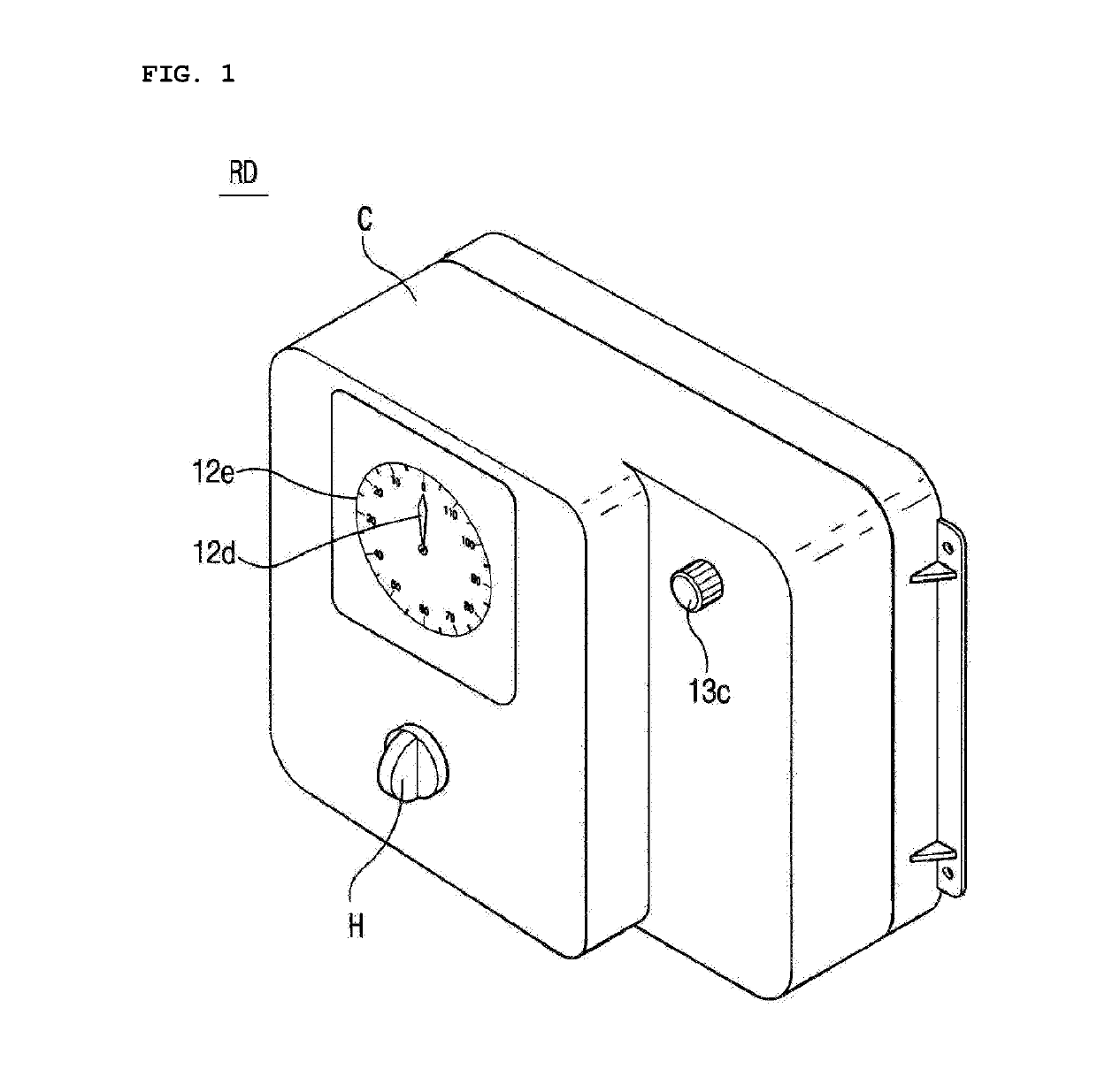
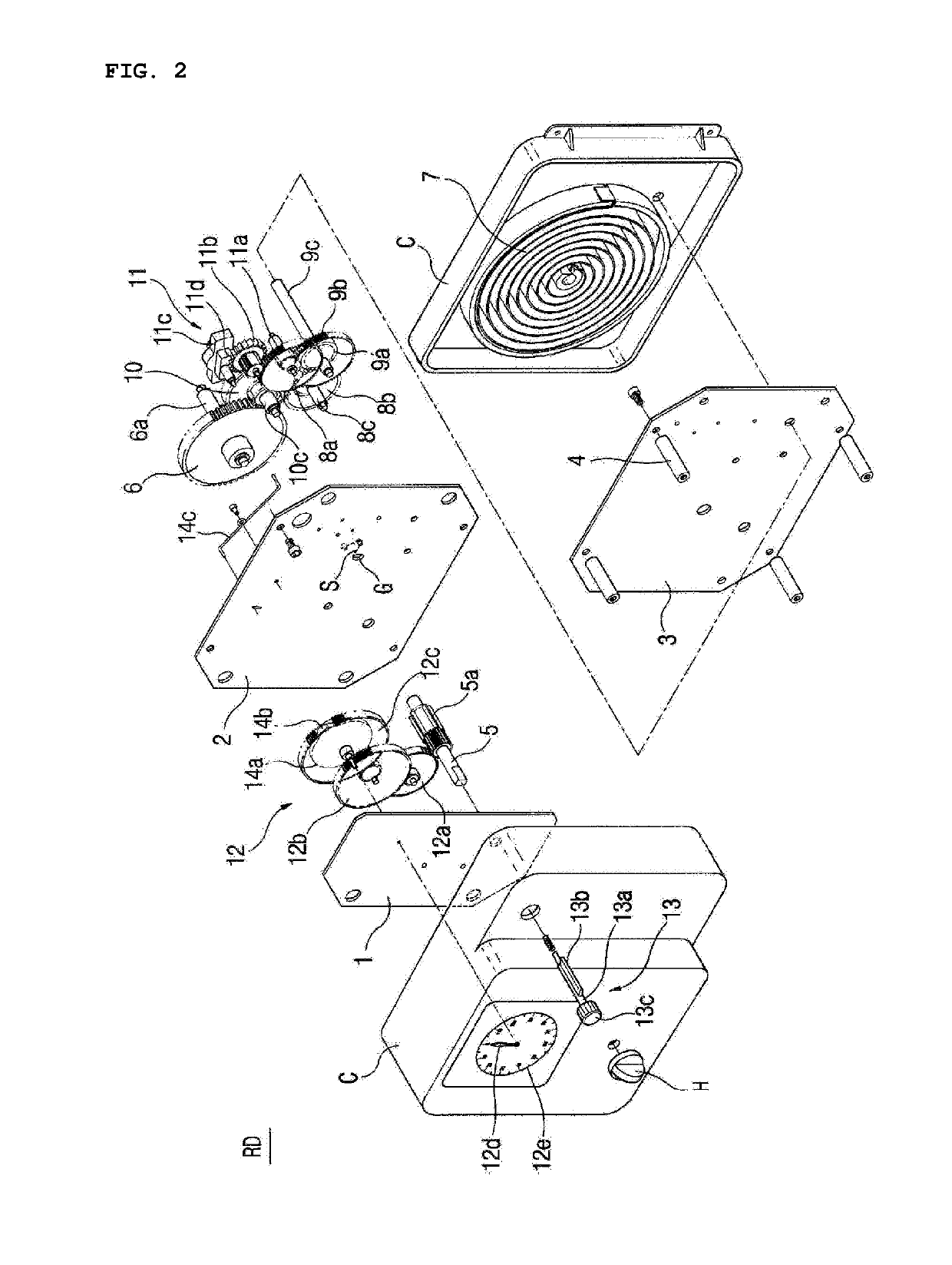
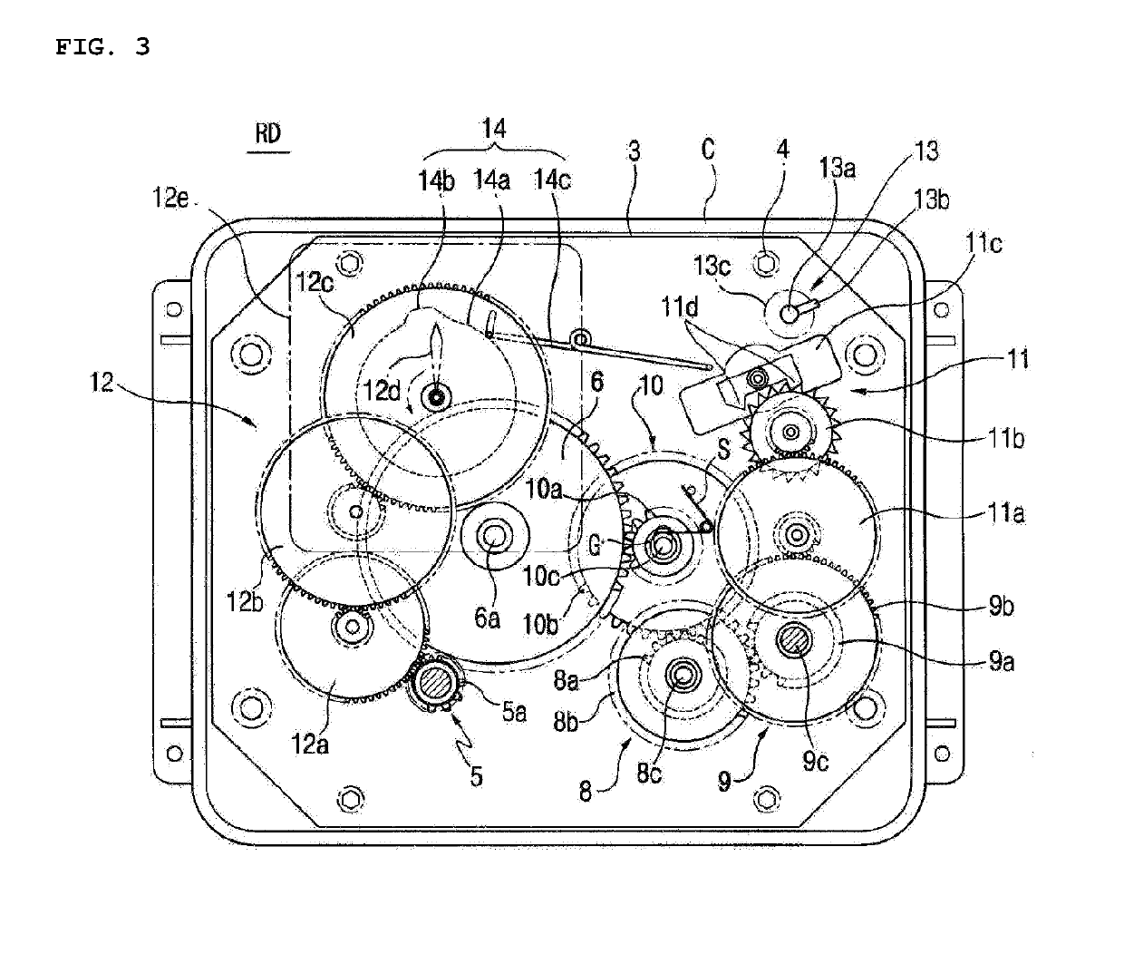
[0047]FIG. 1 is an assembled perspective view of a rotational force generating device using a clock spring (hereinafter, referred to as a clock-spring based rotational force generating device) according to the present invention, FIG. 2 is an exploded perspective view of the clock spring-based rotational force generating device according to the present invention, and FIG. 3 is a front view of the clock spring-based rotational force generating device according to the present invention.

[0048]Reference characters 1, 2, and 3 respectively denote first, second, and third diaphragms fastened by a plurality of fastening means in a manner of being arranged at predetermined intervals. The first, second, and third diaphragms 1, 2, and 3 are acc...


PUM


Abstract

Disclosed is a clock spring-based rotational force generating device capable of allowing a user to freely adjust rotation speed of an output shaft and preventing the output shaft from rotating slowly or never rotating due to an weakened unwinding force of a spiral spring in the late period of an operation span of the spiral spring. The device includes an input shaft, a main drive gear receiving the rotational force of the input shaft, a spiral spring wound around a main drive gear shaft, a speed gear to increase the rotational force of the main drive gear, a power transmission control gear sliding up and down to control transmission of the rotational force of the main drive gear to the speed gear, an output shaft outputting the rotational force increased by the speed gear, and a rotation speed control means for controlling the rotation speed of the output shaft.

Description

TECHNICAL FIELD[0001]The present invention relates to a rotational force generating device using a clock spring. More particularly, the present invention relates to a rotational force generating device using a clock spring, the device being capable of allowing a user to freely adjust the rotation speed (revolutions per minute (RPM)) of an output shaft thereof and of preventing the rotation of the output shaft from being stopped due to weakening of the rotational force of the output shaft which is attributable to weakening of an unwinding rotational force of a spiral spring in the second half period of an operation span of the output shaft.BACKGROUND ART[0002]Examples of rotational force generating means include a motor, a prime mover, and a battery. These rotational force generation means have found their applications in various industrial fields.[0003]In order to operate the rotational force generating means described above, electricity, or a liquid fuel, or a solid fuel is require...

Claims


Application Information

Patent Timeline
Patent Type & Authority Applications(United States)
IPC IPC(8): F03G1/06F03G1/02F03G7/08
CPCF03G1/06F03G1/02F03G7/08F03G2730/01F03G1/08F03G1/022
Inventor KIM, BU JA
Owner GREENIMT CO LTD
Why Eureka
Try Eureka