Methods for operating a motor vehicle driven by an internal combustion engine and by two electrical machines

a technology of internal combustion engine and motor vehicle, which is applied in the direction of engine-driven generators, machines/engines, multi-dynamo-motor starters, etc., can solve the problems of reducing efficiency and affecting the tractive force, and achieves wide gear ratio range, good efficiency, and good rpm

Inactive Publication Date: 2005-02-08
ROBERT BOSCH GMBH
View PDF9 Cites 63 Cited by
  • Summary
  • Abstract
  • Description
  • Claims
  • Application Information

AI Technical Summary

Benefits of technology

The methods of the invention having the definitive characteristics of the bodies of the independent claims have the advantage that compared to the known method, still more-efficient operation is possible, because on the one hand a circulating mechanical power flow in the transmission is at least reduced; on the other, there is no interruption of tractive force from selection of a gear. The power of the engine can already be made available upon startup. Moreover, bucking of the motor vehicle upon selection of a gear is precluded from occurring. Furthermore, an engine brake can be dispensed with.
Starting up electrically with two forward gears that are far apart from one another and are disposed each in different power paths, there is the advantage that even at low vehicle speeds, the electrical machines can be operated at a favorable rpm and with good efficiency. Moreover, a relatively wide gear ratio range is covered with this gear combination, and at the same time engine starting from the electrical driving mode is made possible. The gear ratio range covered is especially wide if the startup is done with first gear and the highest gear, in particular sixth gear.
If electrical starting is done with reverse gear in one power path and second gear in the other power path, then vibration especially upon engine starting is well damped. This effect is improved still further if the amount of the gear ratio of reverse gear is equal to the amount of the gear ratio of second gear.

Problems solved by technology

Moreover, upon startup or starting of the internal combustion engine, one additional gear must first be selected, which at that instant in the affected power path causes an interruption in the tractive force.
Both situations involve losses, which reduce the efficiency.

Method used


Image

  • Methods for operating a motor vehicle driven by an internal combustion engine and by two electrical machines
  • Methods for operating a motor vehicle driven by an internal combustion engine and by two electrical machines
  • Methods for operating a motor vehicle driven by an internal combustion engine and by two electrical machines

Examples


Embodiment Construction

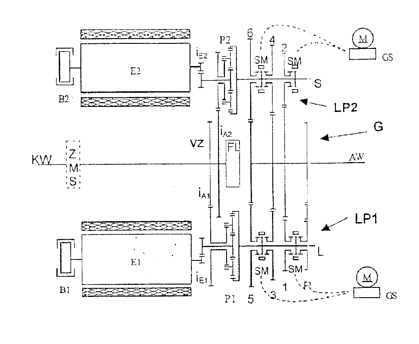
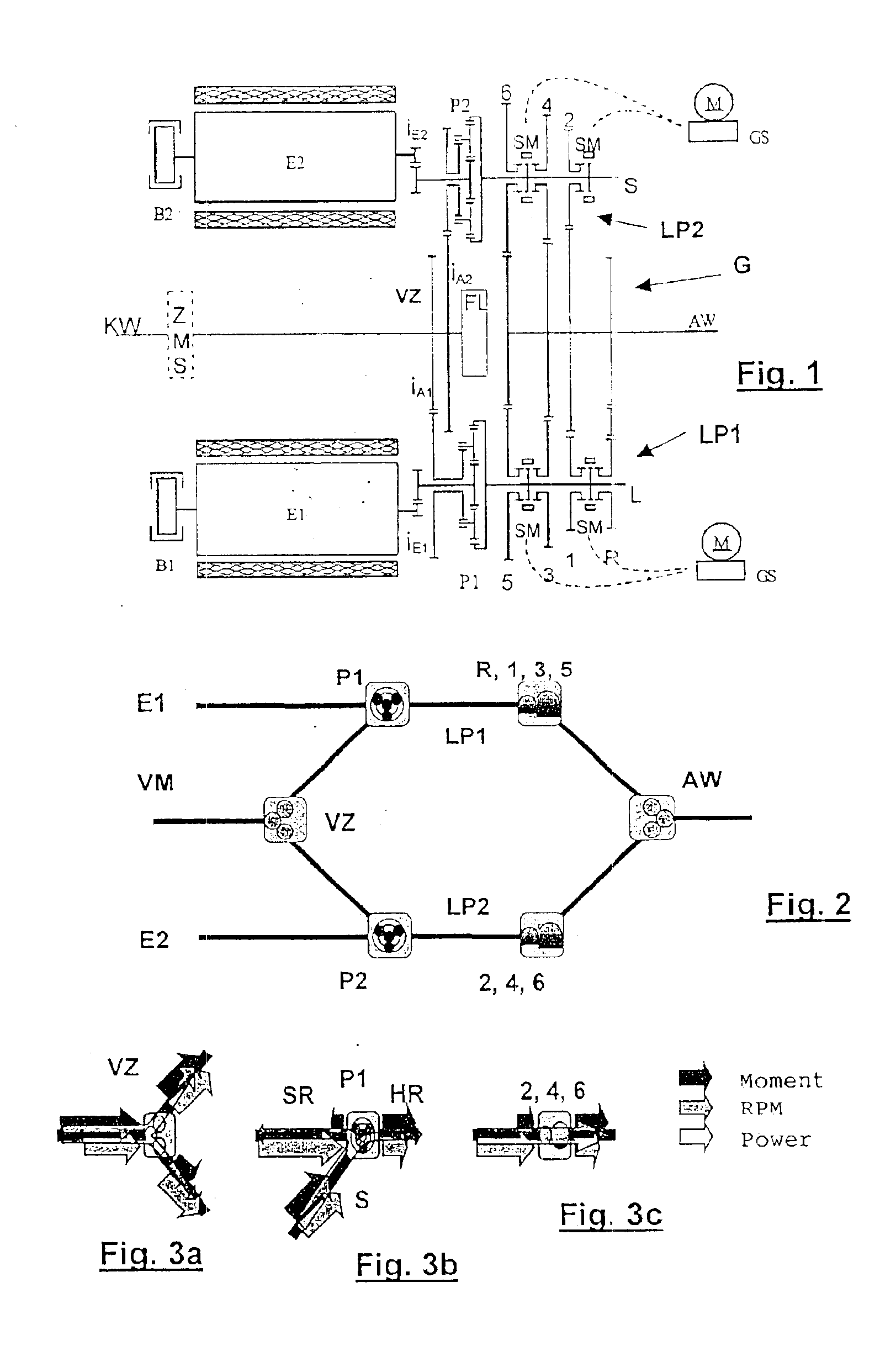
In FIG. 1, part of a drive train of a motor vehicle, in particular a transmission G, is shown, of the kind already known from DE 199 03 936 A1. Here, the planet wheels of two planetary gears P1 and P2 are driven by a crankshaft KW or input shaft, driven by the internal combustion engine VM (FIG. 2), via a two-mass flywheel ZMS and via two gear ratios iA1 and iA2 of a branching point VZ. Instead of the planetary gears P1 and P2, other epicyclic gears can also be used, such as friction wheel epicyclic gears. The planetary gears P1, P2 are more suitable, however, because of their efficiency. The two-mass flywheel ZMS brings about a reduction in the excitation of vibration in the transmission G from the engine VM.

Two electrical machines E1 and E2 are connected to the sun wheels of the corresponding planetary gears P1 and P2 via the gear ratios iE1 and iE2. The electrical machines E1, E2, which are connected both to one another, for instance via an electrical intermediate circuit, and to...


PUM


Abstract

Two methods for operating a motor vehicle driven by an internal combustion engine (VM) and by two electrical machines (E1, E2) are proposed. The motor vehicle has a transmission (G) with two power paths (LP1, LP2) controllable independently of one another. Each power path (LP1, LP2) is coupled via a respective epicyclic gear (P1, P2) to one of the electrical machines (LP1, LP2) and to the input shaft (KW) of the transmission (G) and can be coupled via shiftable gears (1, 2, 3, 4, 5, 6, R) to the output shaft (AW) of the transmission (G). The object is to make it possible to operate the motor vehicle more efficiently. To reduce circulating mechanical power flow between the two power paths (LP1, LP2), particularly in the boost mode or upon recuperation of braking energy, the gear combination (1, 2, 3, 4, 5, 6, R) is varied, or the engine rpm is lowered, or only one electrical machine (E1, E2) is used as a generator. More-comfortable operation is additionally achieved in that upon electrical starting, the engine (VM) is started simultaneously.

Description

BACKGROUND OF THE INVENTIONThe invention is based on a method as generically defined by the preamble to the independent claims.One such method is known for instance from German Patent Disclosure DE 199 03 936 A1. In this method, a motor vehicle is operated at least intermittently by an internal combustion engine and at least intermittently by at least one of two electrical machines. The motor vehicle has a transmission, with an input shaft, an output shaft, and two independently controllable power paths. Each power path is coupled to one of the two electrical machines and to the input shaft via a respective epicyclic gear and can be coupled to the output shaft via shiftable gears. If one gear is selected in each power path, then power can be transmitted to the output shaft simultaneously over both power paths.This method has the advantage that with a transmission of relatively simple mechanical construction, good efficiency can be achieved. However, the possibility exists that a cir...

Claims


Application Information

Patent Timeline
Patent Type & Authority Patents(United States)
IPC IPC(8): B60K6/04B60K6/00F16H3/72F16H3/44B60K1/02B60K1/00B60K6/36B60K6/365B60K6/445B60K6/547B60L50/16B60W10/06B60W10/08B60W10/10B60W10/18B60W20/00F02D29/02F16H61/02
CPCB60K6/365B60K6/445B60K6/547B60W10/06B60W10/08B60W20/00F16H3/728B60K6/36B60K1/02Y10T477/33B60K2006/541B60L2240/423B60L2240/443B60W2510/0657B60W2510/083B60W2710/0666B60W2710/083F16H37/0826F16H2200/0052Y02T10/6286Y10S903/909Y10S903/91Y10S903/919Y02T10/642Y02T10/6239Y10T477/23Y02T10/62Y02T10/64B60K2006/268
Inventor TUMBACK, STEFANSCHNELLE, KLAUS-PETER
Owner ROBERT BOSCH GMBH
Why Eureka
Try Eureka