Method, system and apparatus for realizing loop protection

A technology of ring network and sub-ring, applied in the field of realizing ring network protection

Inactive Publication Date: 2007-11-21
HUAWEI TECH CO LTD
View PDF0 Cites 47 Cited by
  • Summary
  • Abstract
  • Description
  • Claims
  • Application Information

AI Technical Summary

Problems solved by technology

[0005] Embodiments of the present invention provide a method and system for realizing ring network protection, whi

Method used


Image

  • Method, system and apparatus for realizing loop protection
  • Method, system and apparatus for realizing loop protection
  • Method, system and apparatus for realizing loop protection

Examples


Embodiment 1

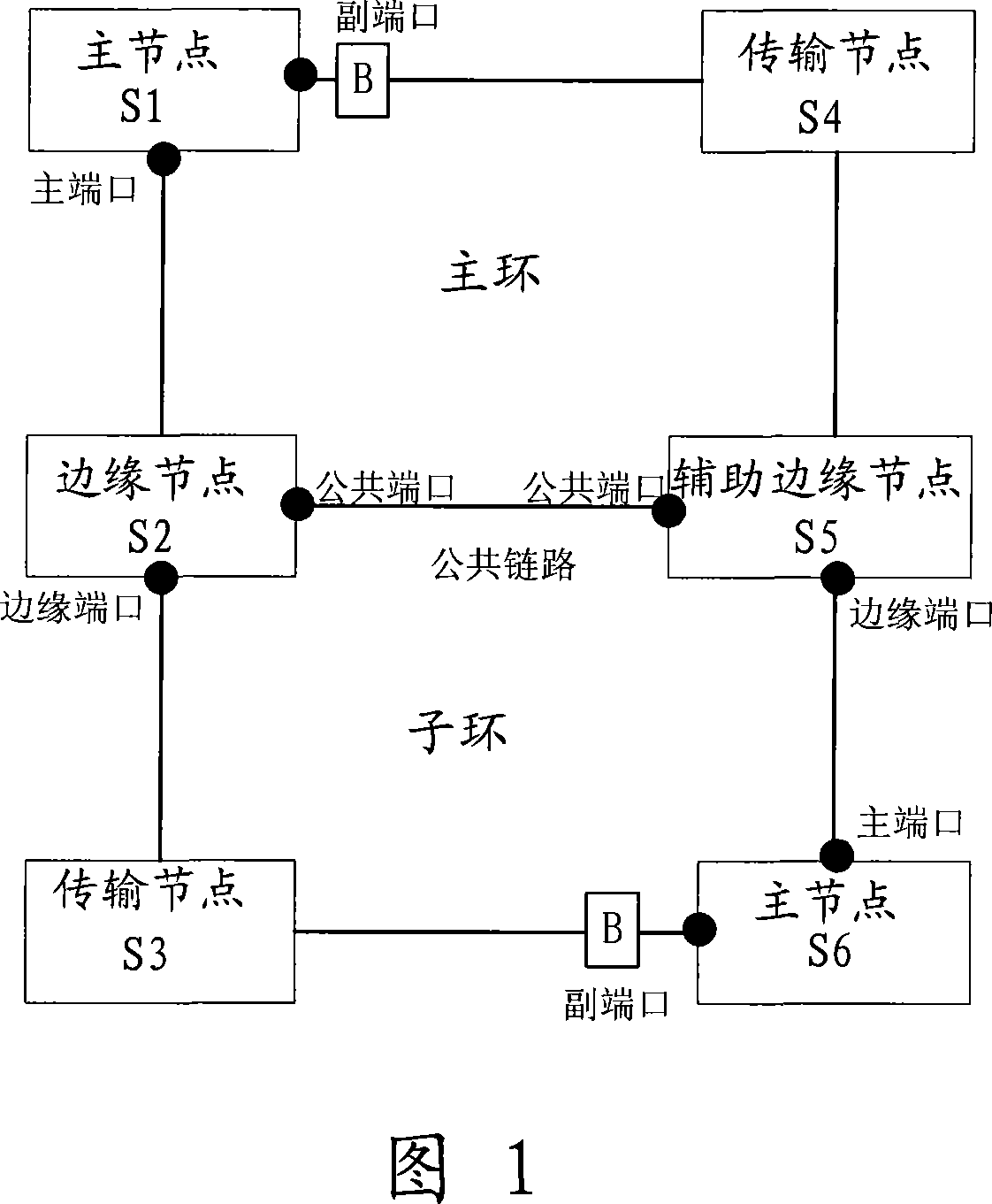
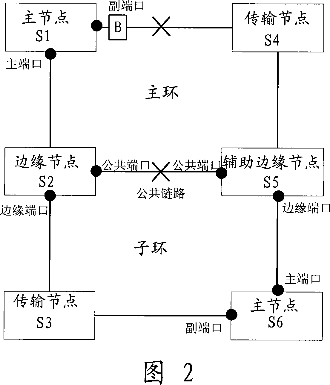
[0049] As shown in Figure 2, the RRPP protocol packets of the subring need to be transmitted between the edge nodes and the edge ports of the auxiliary edge nodes through the channel provided by the main ring, as if the entire main ring is a logical node on the subring, and the subring RRPP protocol packets are transparently transmitted through the main ring. When the sub-ring protocol message channel on the major ring is interrupted (that is, the public link between the major ring and the sub-ring fails, and more than one non-public link fails), after the master node sends a health detection message (HELLO), the Start the FAIL timer, because within the time specified by the FAIL timer, the master node of the sub-ring will not receive the HELLO message sent by itself, so the FAIL timer expires, and the master node of the sub-ring releases the secondary port.

Embodiment 2

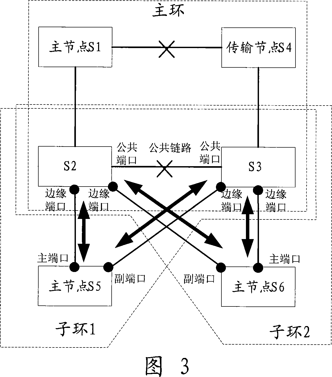
[0051] For the common networking shown in Figure 2, broadcast loops can be avoided. However, for the dual-homing network commonly used in actual networking shown in Figure 3, there are three ring networks in Figure 3, one of which is the main ring, and two are sub-rings, namely sub-ring 1 and sub-ring 2. Among them, sub-ring 1 is composed of main node S5, edge node S2 and auxiliary edge node S3. On sub-ring 1, we can assume that S2 is an edge node and S3 is an auxiliary edge node; Composed of S2 and edge node S3 (here, it is assumed that node S2 and node S3 have different roles in the two sub-rings, so that the subsequent diagram can more clearly show the effect of edge port being blocked. In fact, node S2 and node S3 Whether the roles in each sub-ring are the same does not affect the implementation of the embodiment of the present invention). Dual-homing sub-ring 1 and sub-ring 2 are connected to each other through nodes S2 and S3, forming a ring. When the sub-ring protocol ...

Embodiment 3

[0067] The embodiment of the present invention also provides a system for realizing ring network protection. The system includes N intersecting ring networks (N is a natural number greater than or equal to 2), one of which is a main ring, and N-1 is a sub-ring. There is one and only one master node in each ring network. The main port of the master node forwards data packets and protocol packets. When the secondary port is blocked, only protocol packets are forwarded. Each sub-ring intersects with the main ring at two nodes, respectively. is the edge node and the auxiliary edge node, and the edge node and the auxiliary edge node are directly connected,

[0068] When the auxiliary edge node detects that the sub-ring protocol message channel on the main ring is interrupted, it notifies the edge node of the sub-ring that the sub-ring protocol message channel on the main ring is interrupted;

[0069] The edge node, after receiving the notification from the auxiliary edge node, bloc...


PUM


Abstract

The invention is used in ring networks crossed each other (N is a natural number and is greater than or equal 2); wherein, the one is main ring and the N-1 are sub-rings; each ring network only has a main node. The method comprises: when the assistant edge node detects that protocol message channel of sub-ring on the main ring is interrupted, after it receives the notice from the assistant edge node through the edge port, the edge node blocks the edge port, and informs the sub-ring that the edge port of main node is blocked, and indicates the main node of sub-ring to open the standby port. The invention also opens a system and a network apparatus thereof.

Description

technical field [0001] The present invention relates to the field of communication technology, in particular to a method, system and device for realizing ring network protection. Background technique [0002] In Ethernet Automatic Protection Switching (EAPS, Ethernet Automatic Protection Switching), it is considered that most network applications are based on a ring. In this simple environment, traffic switching can be realized within 50 milliseconds through a simplified protocol instead of STP. (Spanning tree protocol, spanningtree protocol) and other protocols complete the switching after a relatively long convergence time. [0003] The main implementation mechanism of EAPS is: set a master node in the ring network, and set a master port and a slave port on the interface of the master node on the ring. Normally, the slave port is in a blocked state and only listens to protocol messages; The port periodically sends a ring integrity detection message (that is, sends a hello...

Claims


Application Information

Patent Timeline
IPC IPC(8): H04L12/437H04L12/24
Inventor 钱锋周贇
Owner HUAWEI TECH CO LTD
Why Eureka
Try Eureka