Laser system with pulse duration switch

A technology of lasers and optical switches, applied in lasers, laser parts, phonon exciters, etc., can solve the problems of slow tunability and large tunability of movable gratings

Pending Publication Date: 2022-02-25
IPG PHOTONICS CORP
View PDF3 Cites 0 Cited by
  • Summary
  • Abstract
  • Description
  • Claims
  • Application Information

AI Technical Summary

Problems solved by technology

However, movable gratings are bulky and their tunability is slower than that of acousto-optic pulse shapers such as the commercially available Dazzler

Method used


Image

  • Laser system with pulse duration switch
  • Laser system with pulse duration switch
  • Laser system with pulse duration switch

Examples


Embodiment Construction

[0043] In the drawings, each identical or nearly identical component that is illustrated in various figures is represented by a like numeral. For purposes of clarity, not every component may be labeled in every drawing.

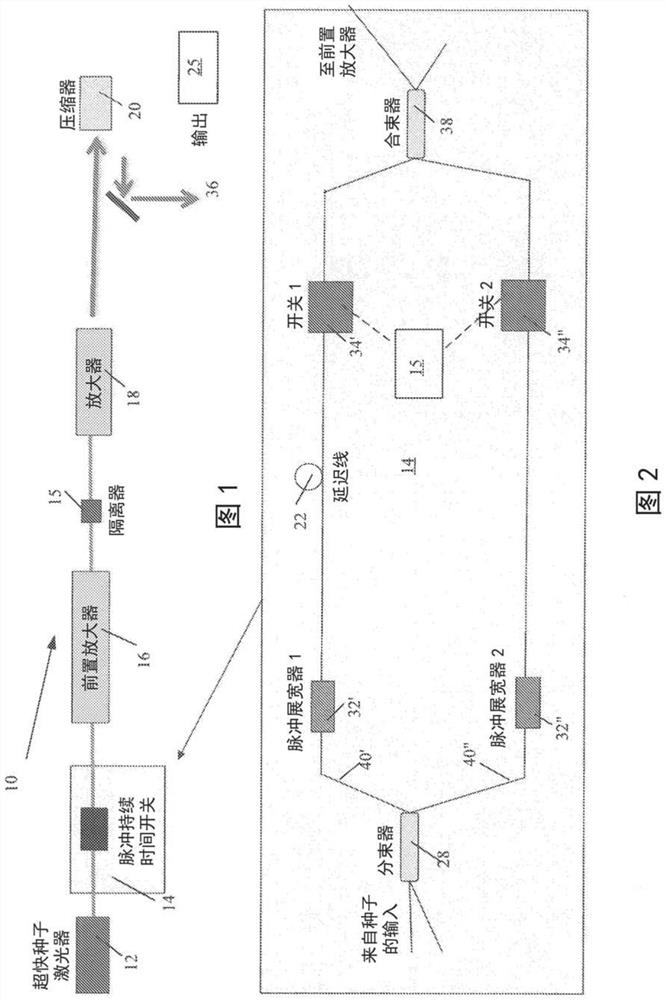
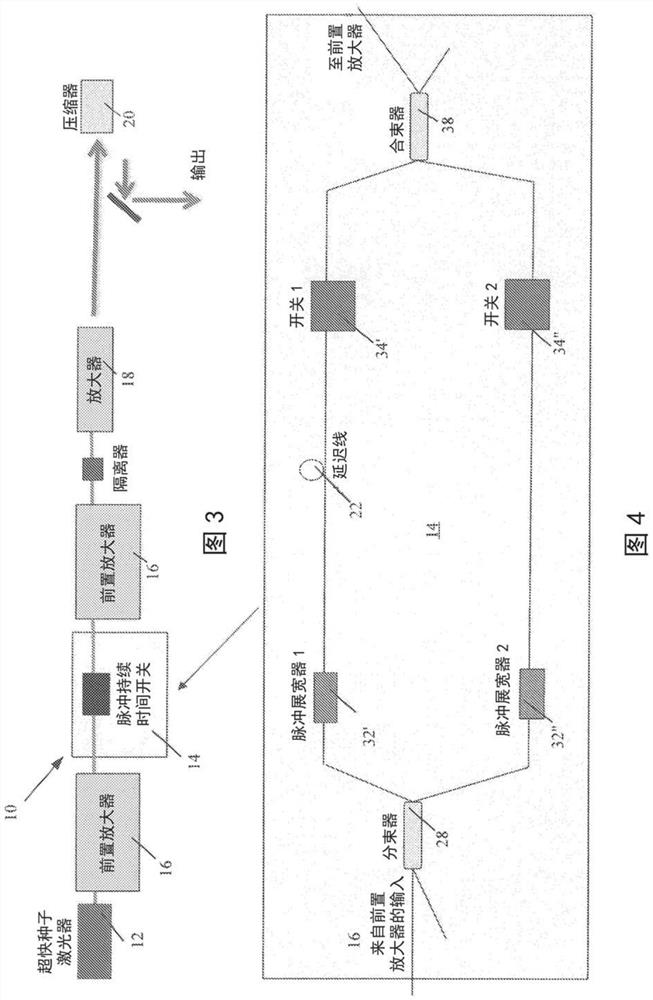
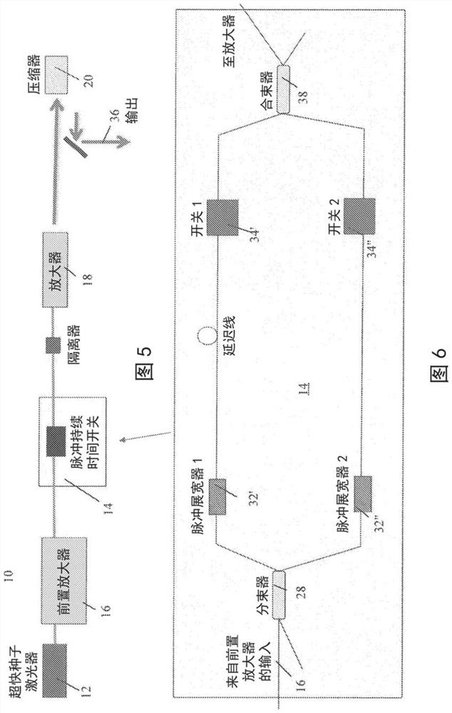
[0044] The laser system of the present invention is based on chirped pulse amplified laser technology and includes: a high speed pulse duration switch assembly operable to pass one or more copies of a pulse of desired duration while blocking or delaying other pulse durations Output. In the laser system of the present invention, proper dispersion management and optionally controllable adjustment of the spectral width of the dispersive elements (e.g., stretcher and compressor, hereinafter also referred to as upstream dispersive element and downstream dispersive element respectively) to set the pulse duration. Several schematic diagrams illustrating the inventive concept are discussed below.

[0045] refer to figure 1 , image 3 , Figure 5 , Figure 7 , ...


PUM


Abstract

A CPA ultrashort pulse laser system is configured with a beam splitter dividing each ultrashort pulse from a seed laser into at least two replicas which propagate along respective replica paths. Each replica path includes an upstream dispersive element stretching respective replicas to different pulse durations. The optical switches are located in the respective replica paths upstream or downstream from upstream dispersive elements. Each optical switch is individually controllable to operate at a high switching speed between on and off positions so as to selectively block one of the replicas or temporally separate the replicas at the output of the switching assembly. The replicas are stretched so that a train of high peak power ultrashort pulses each are output with a pulse duration selected from a fs - ns range and peak power of up to a MW level.

Description

technical field [0001] The present invention relates to ultrafast fiber laser systems operable to rapidly and controllably switch pulse durations at extremely high speeds to perform different material processing tasks at higher production rates and at reduced cost. Background technique [0002] The pulse duration of a laser is a key parameter for optimal laser machining. Different materials often require very different pulse durations for optimum machining quality and processing speed. Laser processing of heterogeneous materials, composite materials or multi-material or multilayer components therefore often requires multiple lasers operating at different pulse durations, at prohibitive costs. Furthermore, different desired types of micromachining (eg, drilling, grooving, marking, engraving, cutting, grinding, scribing, etc.) may also require a range of optimal pulse durations. It would be advantageous to be able to perform multiple types of machining on the same component ...

Claims


Application Information

Patent Timeline
Patent Type & Authority Applications(China)
IPC IPC(8): H01S3/10
CPCH01S3/0057H01S3/2316H01S3/2383H01S3/10023H01S3/06758H01S3/10046H01S3/2375H01S3/0092H01S3/1003H01S3/127H01S3/1603H01S3/1643
Inventor 亚历克斯·尤西姆大卫·克拉克伊格尔·山马尔特瑟夫乔·安塔斯贾斯汀·巴尔萨卢
Owner IPG PHOTONICS CORP
Why Eureka
Try Eureka