Angular rate sensor

An angular velocity sensor and angular velocity technology, applied in the direction of measuring acceleration, gyro effect for speed measurement, instruments, etc., can solve problems such as noise, separation, and unintended vibration, and achieve the effects of improving sensitivity, reducing noise, and high sensitivity

Inactive Publication Date: 2007-11-28
HITACHI METALS LTD
View PDF2 Cites 32 Cited by
  • Summary
  • Abstract
  • Description
  • Claims
  • Application Information

AI Technical Summary

Problems solved by technology

In addition, when there is an acceleration in the same direction as the detected vibration, there will be a displacement in the same direction as the detected vibration, which cannot be separated from the target vibration, so there will be noise

Method used


Image

  • Angular rate sensor
  • Angular rate sensor
  • Angular rate sensor

Examples


Embodiment Construction

[0029] Several embodiments of the present invention are described below with the accompanying drawings. In the drawings of the respective embodiments, the same symbols represent the same components or equivalent components.

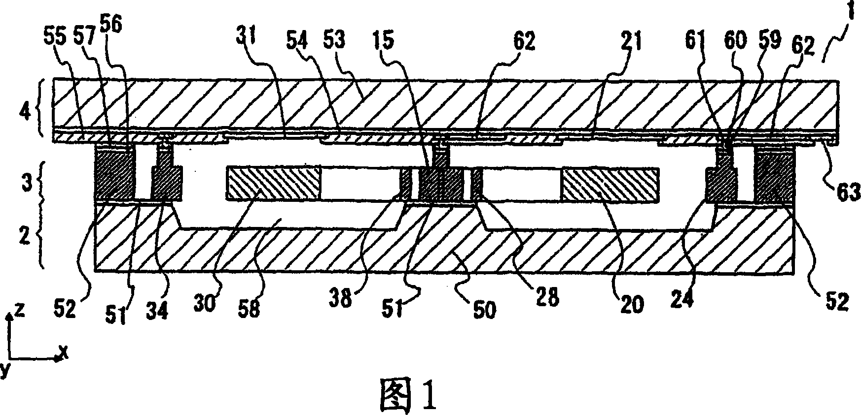
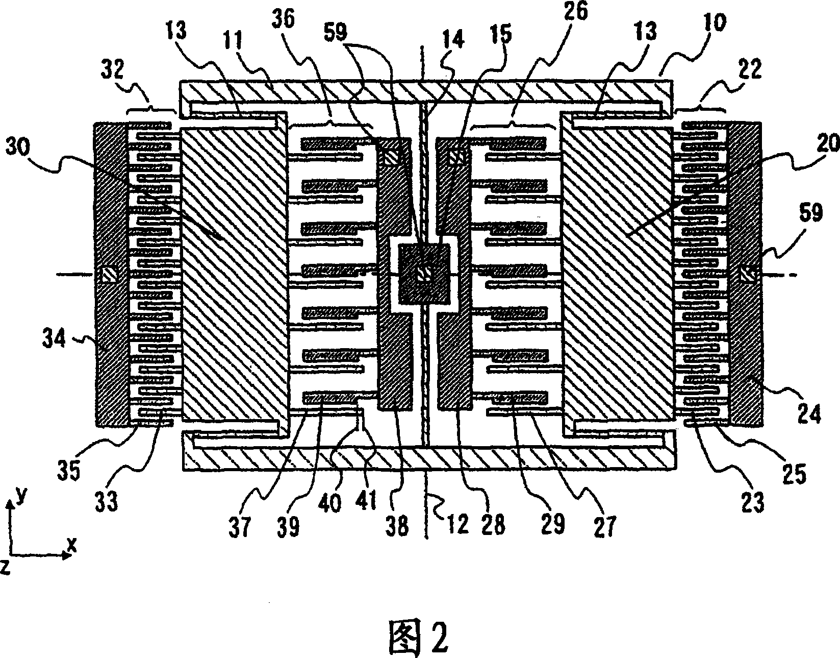
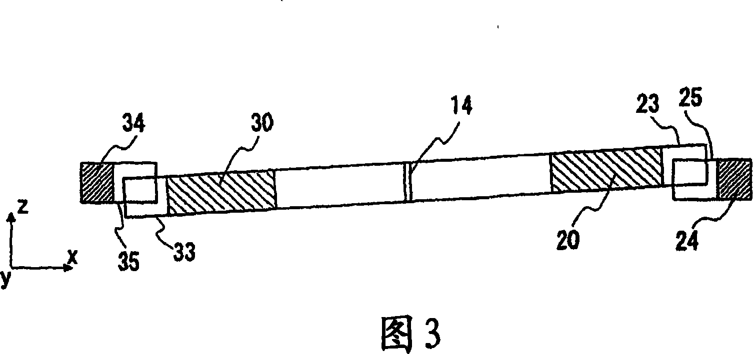
[0030] An angular velocity sensor according to a first embodiment of the present invention will be described with reference to FIGS. 1 to 3 . FIG. 1 shows a schematic cross-sectional view of this embodiment, and FIG. 2 shows a schematic plan view of an element substrate of this embodiment.

[0031] As shown in FIG. 1 , an angular velocity sensor 1 of this embodiment is composed of three layers of a support substrate 2 , an element substrate 3 , and a wiring substrate 4 . The movable part of the sensor is formed in the element substrate 3 , and the structure of the element substrate 3 includes a part engaged and fixed with the support substrate 2 and a part separated from the support substrate 2 and displaceably supported in the element substrate 3 .

[...


PUM


Abstract

An angular rate sensor formed into a planar shape, which detects an angular rate around a first axis in the plane, includes a rotating oscillator rotatably supported in the plane and around the rotational axis in a direction of a second axis perpendicular to the first axis; vibration generating means which rotationally vibrates the rotating oscillator; and a first detecting oscillator and a second detecting oscillator which are disposed inside the rotating oscillator and separately on the right side and the left side of the rotational axis, and which are supported as being displaceable in a direction of the second axis. A first detecting unit and a second detecting unit, which detect vibrations of the respective first and second detecting oscillators in the direction of the second axis due to the Coriolis force, are respectively provided closer to the rotational axis than the first and second detecting oscillators are.

Description

technical field [0001] The present invention relates to a small sensor for detecting angular velocity. Background technique [0002] As a technology for realizing an angular velocity sensor (gyro sensor), in the field of MEMS (micro-electromechanical systems) in recent years, research on the manufacture of small-sized acceleration sensors that can be mass-produced using silicon substrates, etc. . [0003] The mainstream technology among the above technologies is called a vibrating gyroscope, that is, when the direction of the rotation axis for measuring angular velocity is used as the first axis, the vibrator is vibrated in the direction of the second axis perpendicular to the first axis (driving vibration), and the gyroscope that is proportional to the angular velocity is detected. Ratio, vibration (detection vibration) caused by the Coriolis force generated in the direction of the third axis perpendicular to the first axis and the second axis. [0004] Since the above-me...

Claims


Application Information

Patent Timeline
Patent Type & Authority Applications(China)
IPC IPC(8): G01P3/495G01C19/02G01C19/56G01C19/5712G01C19/574
CPCG01P15/125G01P2015/0814G01C19/5712G01P15/12
Inventor 风间敦中村滋男
Owner HITACHI METALS LTD
Why Eureka
Try Eureka