Support structure for elevated floor assembly

A supporting structure and elevated floor technology, which is applied to local raised floors, building structures, floors, etc., can solve the problems of insufficient rigidity of the supporting structure, time-consuming, troublesome, etc.

Active Publication Date: 2007-11-28
尤尼弗莱尔工业公司
View PDF1 Cites 3 Cited by
  • Summary
  • Abstract
  • Description
  • Claims
  • Application Information

AI Technical Summary

Problems solved by technology

This constitutes rather cumbersome and time-consuming work
In addition, the rigidity of the supporting structure is not enough

Method used


Image

  • Support structure for elevated floor assembly
  • Support structure for elevated floor assembly
  • Support structure for elevated floor assembly

Examples


Embodiment Construction

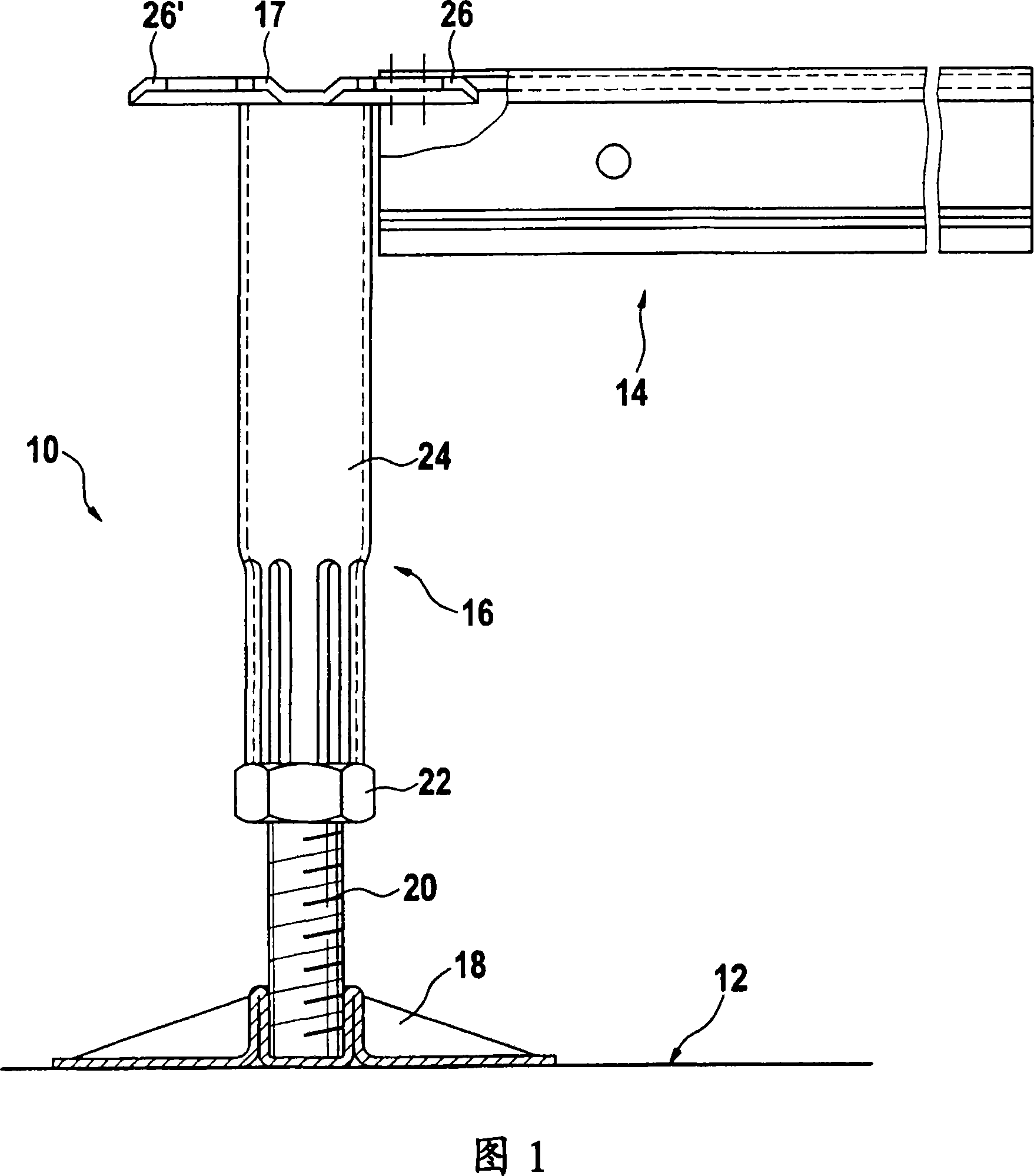
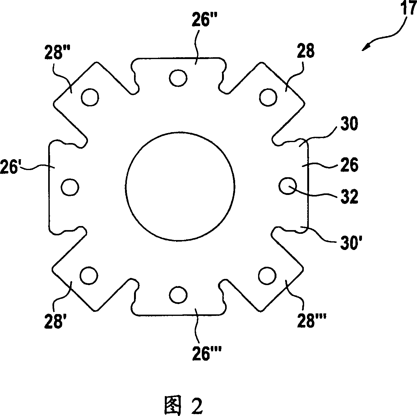
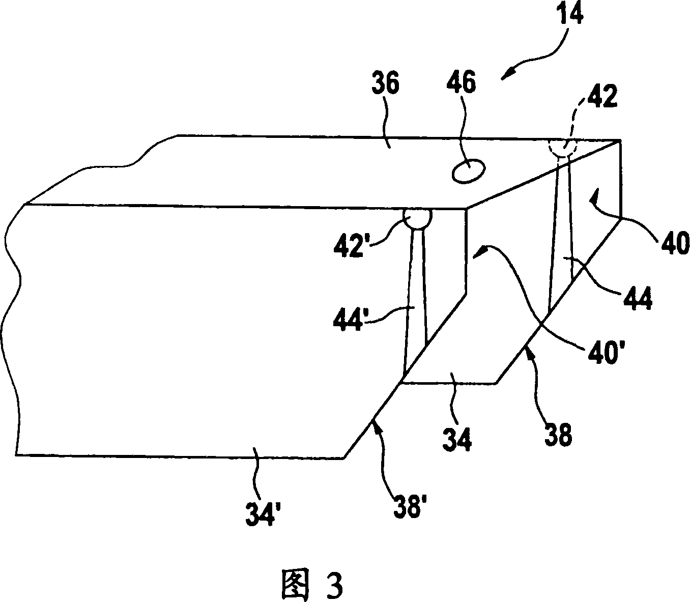
[0019] Figure 1 shows a foundation 10 mounted to a foundation floor 12 to form a support structure together with panel stringers 14, only one of which is partially shown. The base 10 comprises: a column, always indicated with the reference numeral 16 ; a support head 17 , fixed to the upper end of the column 16 ; and a base plate 18 , fixed to the lower end of the column 16 . The column 16 includes a threaded rod 20 , a bearing nut 22 threaded on the threaded rod 20 , and a hollow support tube 24 . The lower end of the support tube 24 is placed above the upper end of the threaded rod 20 and is supported on the upper end by the bearing nut 22 . It can be seen that the support tube 24 can be raised or lowered by screwing the bearing nut 22 on the threaded rod 20 , so that the height of the base 10 can be adjusted freely. The upper end of the support pipe 24 is connected to the support head 17 . The support head typically comprises four or eight support arms to which panel stri...


PUM


Abstract

Support structure for elevated floor assembly comprising a plurality of pedestals (10) and panel stringers (14) coupled between adjacent pedestals (10), each pedestal (10) having a column (16) with a supporting head (17) on an upper end of the column (16) and a base plate (18) on the lower end of the 5 column (16), the supporting head (17) having radially protruding supporting arms (26) for connecting the panel stringers (14) thereto, and each panel stringer (14) having a generally inverted U-shaped cross-section with two generally parallel side portions (34, 34') and an interconnecting portion (36), wherein the interconnecting portion (36) rests on the radially protruding 10 supporting arm (26) of the supporting head (17) of the pedestal (10). According to an important aspect of the invention, at an end portion of the panel stringer (14), at least one of the side portions (34, 34') comprises, on its inner surface (40, 40'), a cavity (42, 42') proximate the interconnecting portion (36) and a guide (44, 44') leading from an edge of the side portion (34, 34') remote from 15 the interconnecting portion (36) to the cavity (42, 42'), and the supporting arm (26) comprises at least one lateral protrusion (30, 30') configured to be received in the cavity (42, 42') when the panel stringer (14) is connected to the supporting arm (26) of the pedestal (10).

Description

technical field [0001] The present invention relates to a support structure for a raised floor assembly. Background technique [0002] Such support structures typically include a plurality of bases, each base comprising: a column; a support head secured to the upper end of the column to be able to support the floor panels of the raised floor assembly; and a base plate secured to the lower end of the column to provide A support platform for placing the base on the foundation floor. The length of the posts is usually adjustable so that the height of the base can be adjusted. To be able to support heavy floor loads, all supporting parts of the foundation are usually made of metal, usually steel in most cases. For increased rigidity and strength, the support structure typically further includes panel stringers bonded between adjacent foundations so as to form a generally square grid when viewed from above. Floor panels are usually placed on panel stringers and form a raised f...

Claims


Application Information

Patent Timeline
Patent Type & Authority Applications(China)
IPC IPC(8): E04F15/024
CPCE04F15/02458E04F15/0247
Inventor 埃里克·彼得·艾萨克
Owner 尤尼弗莱尔工业公司
Why Eureka
Try Eureka