Method and device for the secure operation of a switching device

A switchgear and working technology, applied to the parts of protective switches, electric switches, protective switches, etc., can solve problems such as insecurity

Active Publication Date: 2007-12-05
SIEMENS AG
View PDF0 Cites 20 Cited by
  • Summary
  • Abstract
  • Description
  • Claims
  • Application Information

AI Technical Summary

Problems solved by technology

Since the electrical equipment is therefore in an unsafe state, the switchgear at this time is a potential source of failure

Method used


Image

  • Method and device for the secure operation of a switching device
  • Method and device for the secure operation of a switching device
  • Method and device for the secure operation of a switching device

Examples


Embodiment Construction

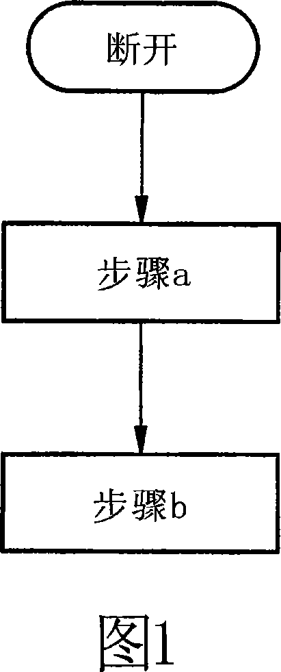
[0076] As shown in Figure 1, after receiving a disconnection signal, the method of the present invention mainly implements the following two steps:

[0077] Step a) identifying whether the movable contact bridge of at least one main contact exceeds a breaking point after opening; and

[0078] Step b) Interrupting further operation of the switching device if said trip point has not been exceeded after a predetermined duration has elapsed.

[0079]Accordingly, it shall be checked whether all main contacts of the switching device have been opened after the opening operation, i.e. in particular after receiving an opening signal requesting opening of the three main contacts of a three-pole switching device . According to the invention, this is achieved by checking whether a specific breaking distance traveled by the movable contact bridge when breaking is greater than a predetermined breaking point. If the detected opening travel of one of the contact bridges remains below this o...


PUM


Abstract

A method and device are disclosed for safely operating a switching device with at least one main contact, which can be switched on or off, and which has contact elements and a moving contact bridge, and with at least one control magnet, which has a moving armature. During switching on and off, the armature acts upon the contact bridge whereby closing and opening the corresponding main contact. At least one embodiment of the method includes the following: a) identifying whether the moving contact bridge of the at least one main contact has surpassed an opening point after the switching off; and b) interrupting the further operation of the switching device when the opening point has not been surpassed after a predetermined period of time.

Description

technical field [0001] The invention relates to a method for safe operation of a switching device according to the preamble of claim 1 and a corresponding arrangement according to the preamble of claim 20 . Background technique [0002] With the aid of switchgear, especially low-voltage switchgear, the current path between the power supply device and the consumer device and its operating current can be switched off. That is, switching current paths with switching devices effectively turns on and off consumers connected in those current paths. [0003] Low-voltage electrical switching devices, such as contactors, circuit breakers or compact starters, have one or more main contacts for switching current paths, which can be controlled by one or more control magnets. These main contacts are mainly composed of a movable contact bridge and a plurality of fixed contacts that can connect electrical equipment and power supply equipment. When the main contact needs to be closed or d...

Claims


Application Information

Patent Timeline
Patent Type & Authority Applications(China)
IPC IPC(8): H01H1/00G01R31/333H01H3/00
CPCH01H1/0015H01H1/20H01H3/001H01H2071/044G01R31/327H01H1/12H01H3/00
Inventor 彼得·哈廷格诺伯特·米特尔迈耶路德维格·尼布勒弗里茨·波尔诺伯特·齐默尔曼
Owner SIEMENS AG
Why Eureka
Try Eureka