
High-current test output clip

A technology for testing output and high current, which is applied in circuit breaker testing, components of electrical measuring instruments, measuring electricity, etc. It can solve the problems of unstable test parameters and large driving force of actuators, etc. The effect of a large energized contact area

Inactive Publication Date: 2007-12-19
上海亿盟电气自动化技术有限公司
View PDF0 Cites 2 Cited by
  • Summary
  • Abstract
  • Description
  • Claims
  • Application Information

AI Technical Summary

Problems solved by technology

[0003] Due to unilateral compression, the cross-sectional area of ​​the soft connection needs to be large, resulting in relatively large driving force of the actuator, which is likely to cause single-line or single-point compression of the busbar surface, resulting in unstable test parameters

Method used


Image

  • High-current test output clip

Examples


Embodiment Construction

[0014] The present invention will be further described below in conjunction with accompanying drawing.

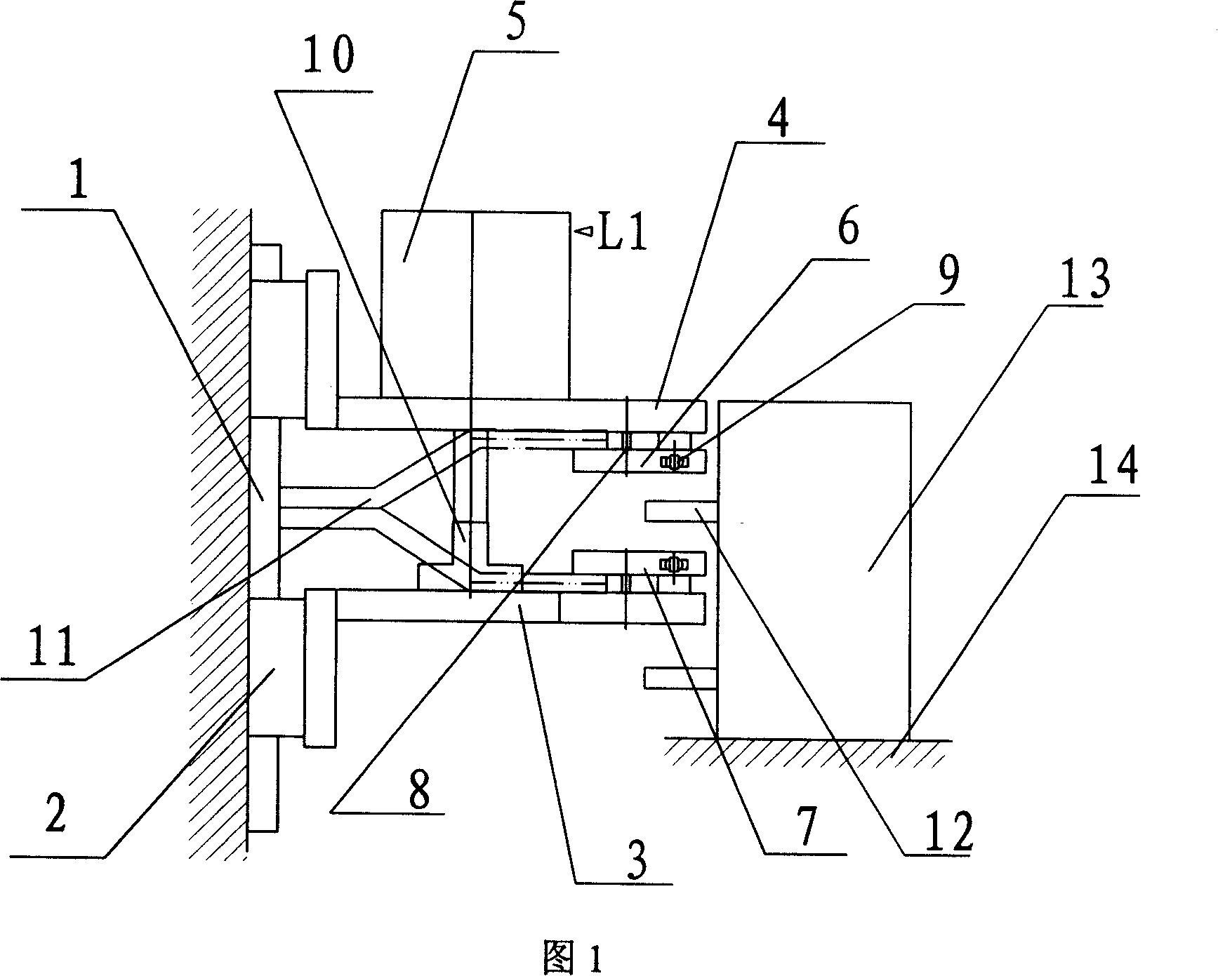
[0015] As shown in Figure 1, the high-current test output chuck includes a guide rail 1, a slide table 2, an upper bracket 3, a lower bracket 4, a cylinder 5, an upper pressing plate 6, a lower pressing plate 7, a guide rod 8, and a joint bearing 9. The sliding table 2 is set on the guide rail 1, the upper bracket 3 and the lower bracket 4 are arranged on the sliding table 2 in parallel, the cylinder 5 is arranged on the upper bracket 3, and the piston rod 10 is tightly connected to the lower bracket 4. Paste, the upper bracket 3 and the lower bracket 4 are respectively connected with the upper pressing plate 6 and the lower pressing plate 7 through the guide rod 8 and the joint bearing 9.

[0016] The cylinder 5 is provided with a magnetic button L1; the upper pressing plate 6 and the lower pressing plate 7 are rectangular with smooth surfaces, and the centerlines of the u...


PUM


Abstract

An output clamping head of large current test is prepared as passing slide table through guide track, arranging top and bottom supports to be parallel on said slide table, setting air cylinder on top support and fitting piston rod of said air cylinder closely to bottom support, connecting top and bottom supports separately to top and bottom press-plates by guide rod and oscillating bearing.

Description

technical field [0001] The invention relates to an output clip, in particular to a large current test output clip. Background technique [0002] Air circuit breakers are commonly used in industrial control. In order to ensure product quality and reliability, a large current test is generally performed before leaving the factory. At present, in mass production, the output chuck for high-current test generally adopts unilateral automatic compression, but this has the following disadvantages: [0003] Due to unilateral compression, the cross-sectional area of ​​the soft connection needs to be large, resulting in a relatively large driving force of the actuator, which is likely to cause single-line or single-point compression on the surface of the busbar, resulting in unstable test parameters. Contents of the invention [0004] The purpose of the present invention is to provide a large-current test output chuck in order to overcome the above-mentioned defects in the prior art...

Claims


Application Information

Patent Timeline
IPC IPC(8): G01R1/02G01R31/00G01R31/327
Inventor 徐惠国尚晓冬
Owner 上海亿盟电气自动化技术有限公司
Learn More