Storage system condition indicator and method

A storage device and storage system technology, which can be applied to the generation of response errors, error detection of redundant codes, input/output to record carriers, etc., and can solve problems such as complex hot backup maintenance.

Inactive Publication Date: 2007-12-26
德洛博公司
View PDF1 Cites 21 Cited by
  • Summary
  • Abstract
  • Description
  • Claims
  • Application Information

AI Technical Summary

Problems solved by technology

Maintenance of hot standbys is often complex, and thus usually handled by

Method used


Image

  • Storage system condition indicator and method
  • Storage system condition indicator and method
  • Storage system condition indicator and method

Examples


Embodiment Construction

[0044] As used in the specification and claims, unless the context requires otherwise, the following terms have the meanings explained below.

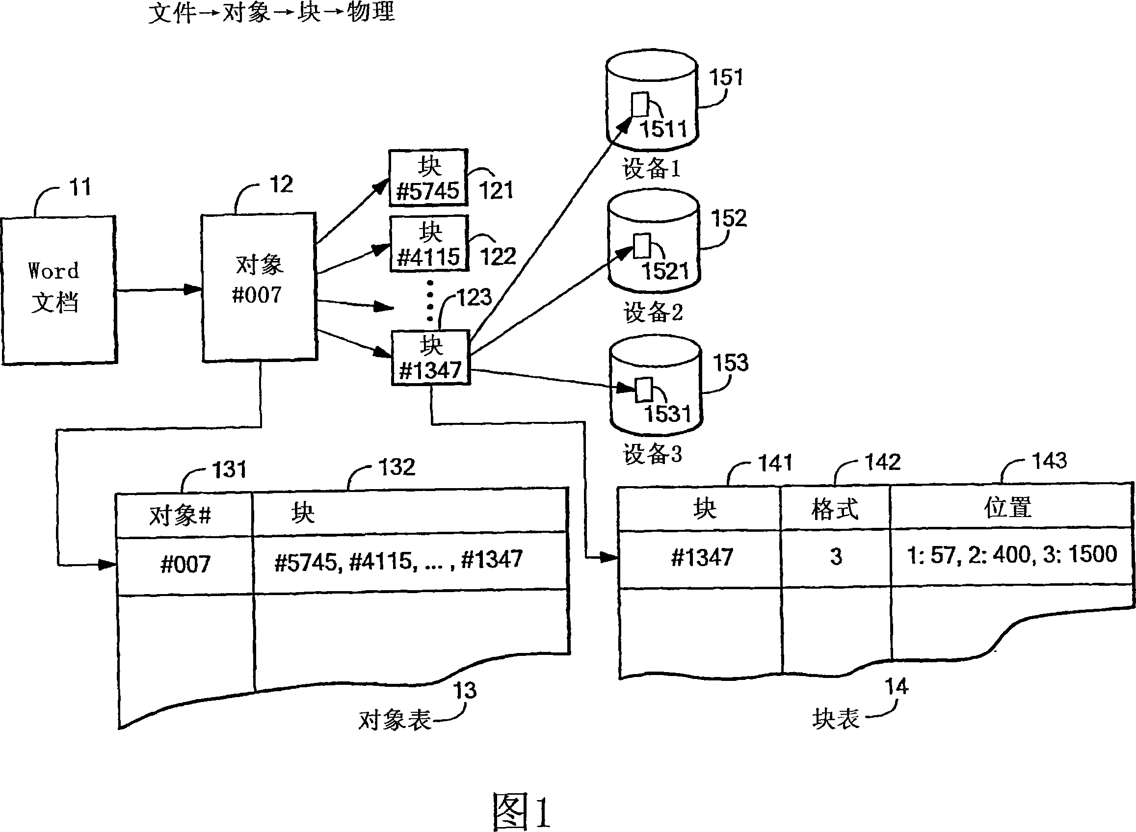
[0045] A "chunk" of an object is an abstracted slice of the object, formed independently of the physical storage used, and is typically a fixed number of contiguous bytes of the object.

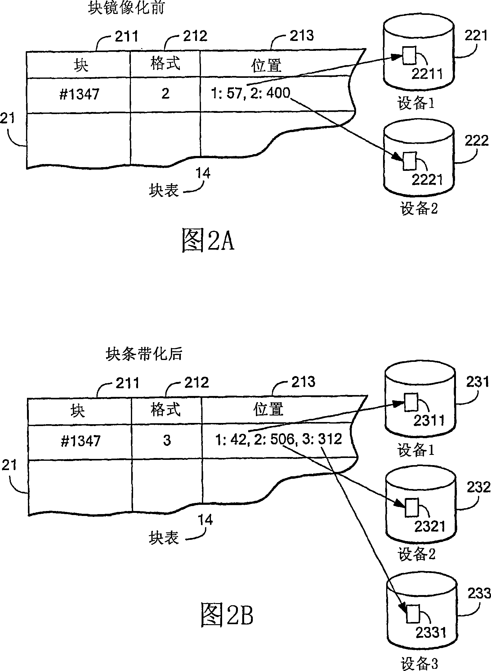
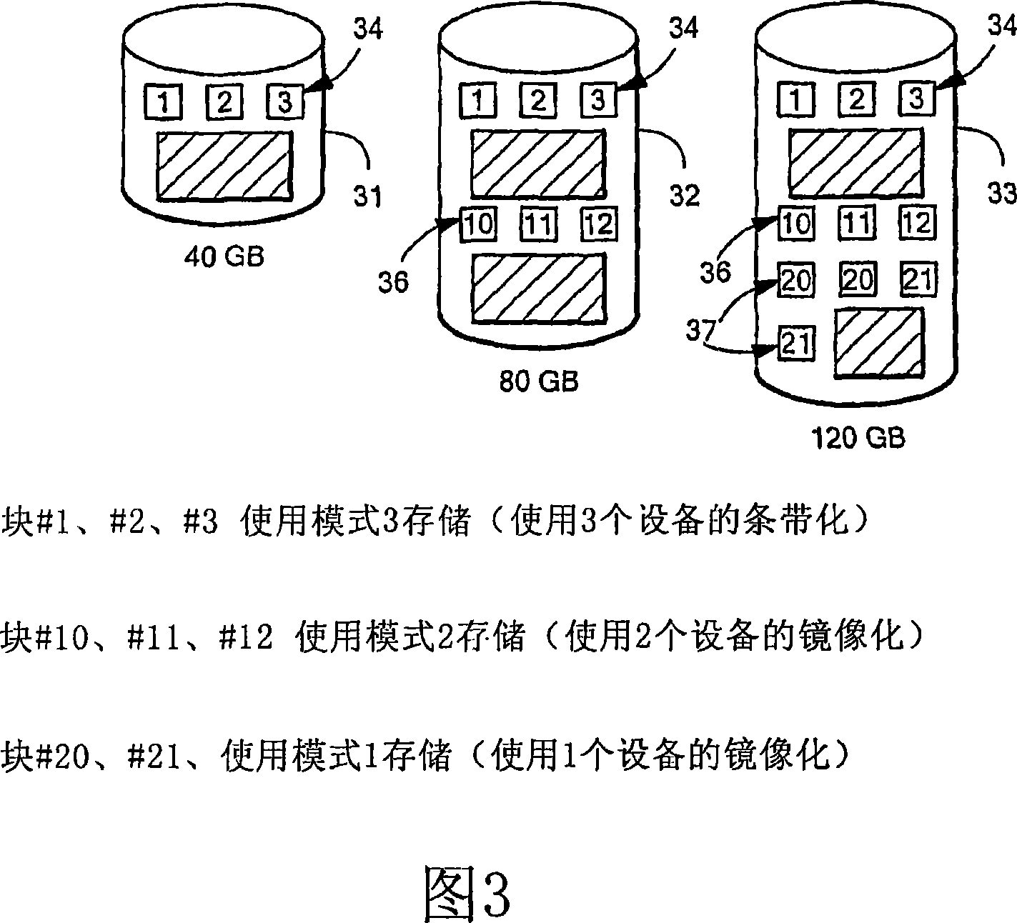
[0046] A fault-tolerant "mode" of data storage refers to a particular way of redundantly distributing data across one or more storage devices, and can be, among others: mirroring (e.g. in a RAID1-like manner), striping ( striping, e.g. in a manner similar to RAID5), RAID6, double parity, diagonal parity, low density parity, turbo, or other redundancy modes or combinations of these redundancy modes.

[0047] When the hash number generated by a given block is generally different from the hash number of any other block, except when other blocks have the same data content as the given block, the hash number of the given block is "unique". (unique)". Tha...


PUM


Abstract

A fault-tolerance storage system allowing storage devices of various sizes to be dynamically expandable and contractile. If possible, data may be stored redundantly across one or more storage devices. With the addition or deletion of the storage devices, a data arrangement across one or more storage devices is automatically configured to provide redundance with appropriate level for data as much as possible. It is possible to reduce the consumption of the storage devices by compression technology based on hashing function. Also disclosed is a technology for releasing unused storage blocks.

Description

technical field [0001] This invention relates to digital data storage systems and methods, and more particularly to those systems and methods that provide fault-tolerant storage. Background technique [0002] The prior art is known to provide redundant disk storage in a mode according to any one of various RAID (Redundant Array of Independent Disks) protocols. A typical disk array using RAID mode is a complex structure that needs to be managed by experienced information technology personnel. Also in many array designs using RAID mode, if the disk drives in the array are of non-uniform capacity, the design may not be able to use any capacity on the drives beyond the capacity of the smallest drive in the array. [0003] One problem with using standard RAID systems is that disk corruption can occur in less frequently used areas of the disk array. In the case of another drive failure, it is not always certain that damage has occurred. In this case, corrupted data may be propa...

Claims


Application Information

Patent Timeline
IPC IPC(8): G06F11/10G06F3/06
Inventor 杰弗里·S·巴拉尔
Owner 德洛博公司
Why Eureka
Try Eureka