Lift installation

A technology for elevators and driving devices, which is applied to elevators, transportation, and packaging in buildings, and can solve problems such as being placed in openings at both ends of the wall of the lift passage, unable to install vibration-damping elements, and inconvenient to operate.

Active Publication Date: 2011-03-30
SHANGHAI MITSUBISHI ELEVATOR CO LTD
View PDF4 Cites 0 Cited by
  • Summary
  • Abstract
  • Description
  • Claims
  • Application Information

AI Technical Summary

Problems solved by technology

In this structure, the vibration damping element cannot be installed between the driving device and the installation beam, and the vibration damping element can only be installed at both ends of the installation beam. In the elevator without machine room, the vibration damping element can only be placed on the wall of the lifting passage Brackets are installed in the openings at both ends, or inside the wall of the lifting passage, and the damping elements are placed on the brackets. The former installation method is inconvenient to operate, and the latter method requires a certain increase in cost.

Method used


Image

  • Lift installation
  • Lift installation
  • Lift installation

Examples


Embodiment Construction

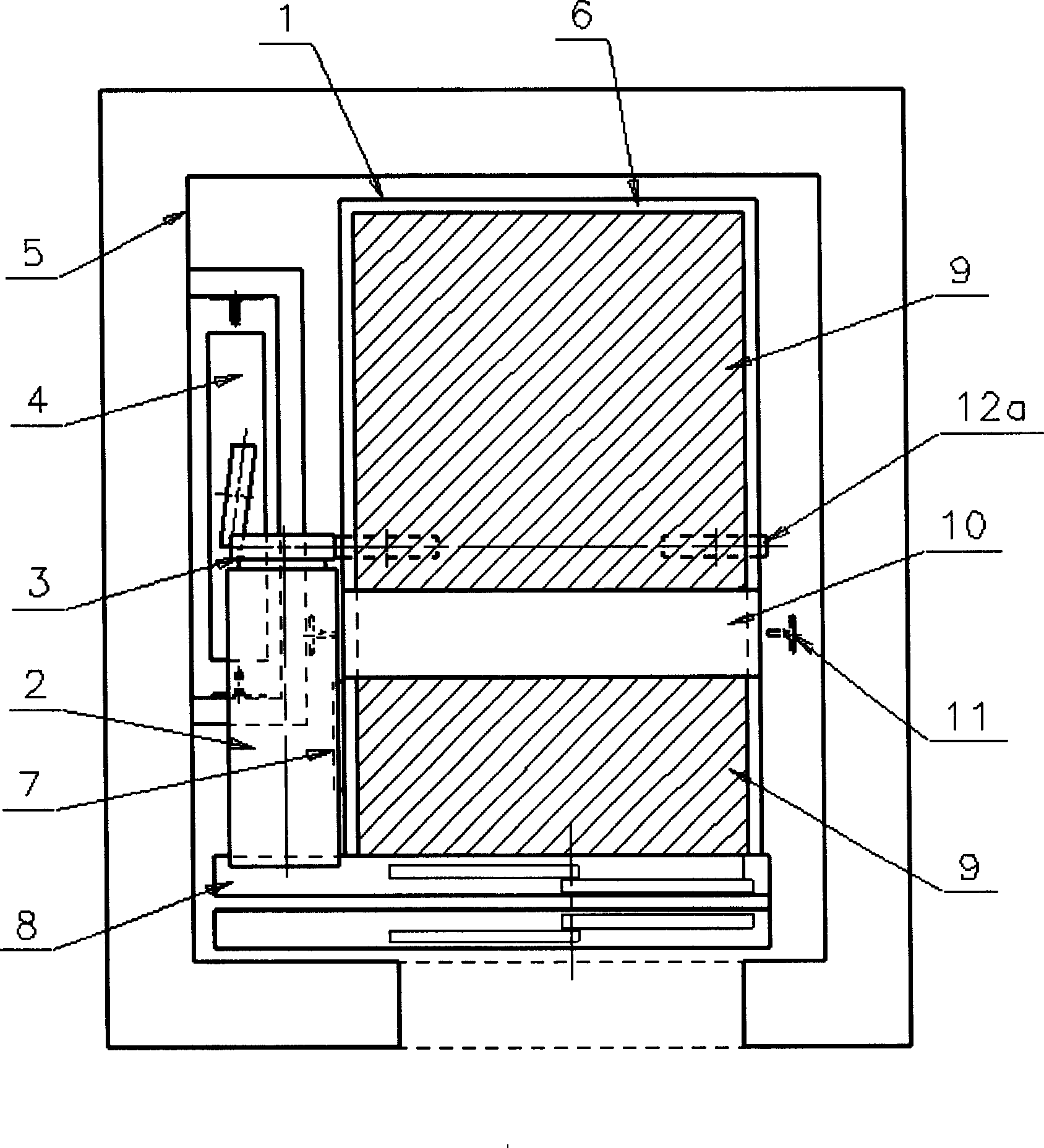
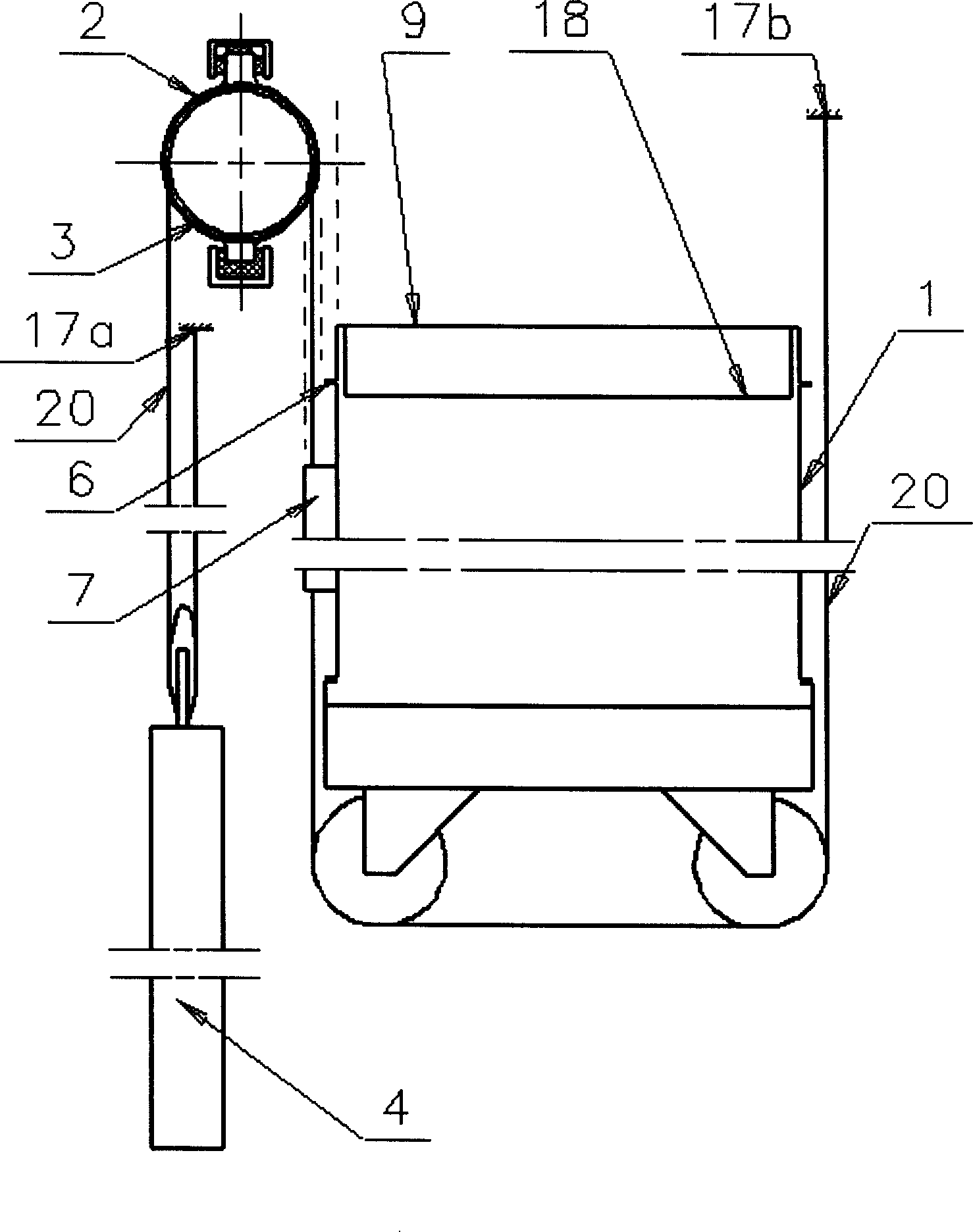
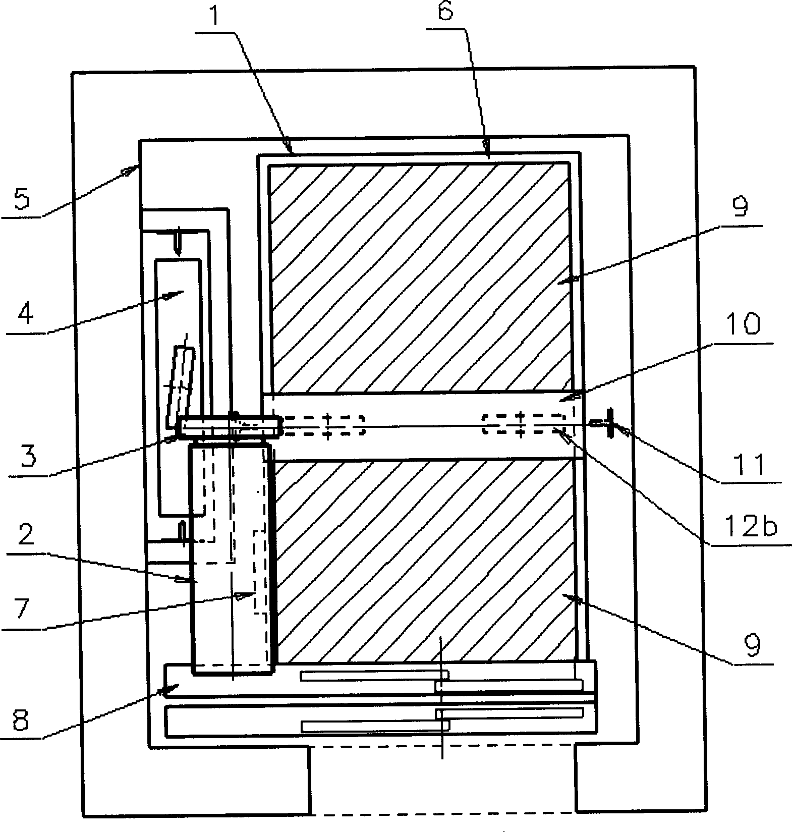
[0025] figure 1 , 2 It is respectively a top view and an elevation view of an embodiment of the present invention, for simplified figures, figure 1 The mounting frame of the drive device 2 is not shown in the figure. It includes the car 1, wherein the upper part of the car 1 may and allows the A plane for the maintenance personnel to stand with the shade 9, and the B plane that is impossible or not allowed for the maintenance personnel to stand on is represented by the joint between the car wall and the car top. 6 and control box 7, door opener 8, the projection of parts such as car frame top beam 10 forms. Because the outside of the car roof of the general car is hat-shaped, the brim part is used to connect with the car wall, and the width is within 40 mm, which does not meet the minimum width requirement for maintenance personnel to stand, so this area belongs to the B plane. The elongated driving device 2 overlaps with the control box 7 and the door opening device 8 of t...


PUM


Abstract

The invention discloses an elevator device, comprising carriage, driving device, installation frame, counter-weight or rope tightening device, and rope used for connecting carriage and counter-weight or rope tightening device and lifting channel accommodating the carriage, the driving device, the counter-weight or rope tightening device and rope. The driving device or the installation frame is overlapped by the projection part of carriage in horizontal face and can not influence operation and safe space for carriage top maintenance. The invention can make maintenance space of carriage top maximum under the condition that damping performance of elevator is guaranteed and the height of top layer can not be influenced.

Description

technical field [0001] The invention relates to a machine room-less elevator device. Background technique [0002] Machine room-less elevators have gradually become the most important and innovative field in the elevator industry. In terms of the overall elevator layout of the machine room-less elevator, the previous layout is relatively simple and conceptual. For example, the projections of the driving device and the car on the horizontal plane do not overlap, that is, the driving device does not interfere with the running space and maintenance of the car. Space; Another arrangement is to artificially limit the maintenance space on the top of the car to ensure the running space and maintenance space of the car. [0003] Chinese invention patent specification CN1092131C (announcement date: October 9, 2002) emphasizes that the projection of the driving device and the car does not overlap, which ensures the running space of the car and the maintenance operation and safety of ...

Claims


Application Information

Patent Timeline
Patent Type & Authority Patents(China)
IPC IPC(8): B66B9/00B66B11/04B66B11/02
Inventor 甘靖戈周双林
Owner SHANGHAI MITSUBISHI ELEVATOR CO LTD
Why Eureka
Try Eureka