
An electric vehicle charging adapter and using method thereof

A technology for electric vehicles and adapters, applied in the direction of electric vehicle charging technology, electric vehicles, charging stations, etc., can solve the problem of high cost, achieve the effect of reasonable structure, reduced requirements on external dimensions and good protection effect

Active Publication Date: 2018-12-25
ZHEJIANG LEAPMOTOR TECH CO LTD
View PDF9 Cites 0 Cited by
  • Summary
  • Abstract
  • Description
  • Claims
  • Application Information

AI Technical Summary

Problems solved by technology

For current electric vehicles, if they want to have both fast charging capability and slow charging capability at the same time, they need to arrange slow charging charging stations and fast charging charging stations on the body, and the cost is relatively high.

Method used


Image

  • An electric vehicle charging adapter and using method thereof
  • An electric vehicle charging adapter and using method thereof
  • An electric vehicle charging adapter and using method thereof

Examples


Embodiment 1

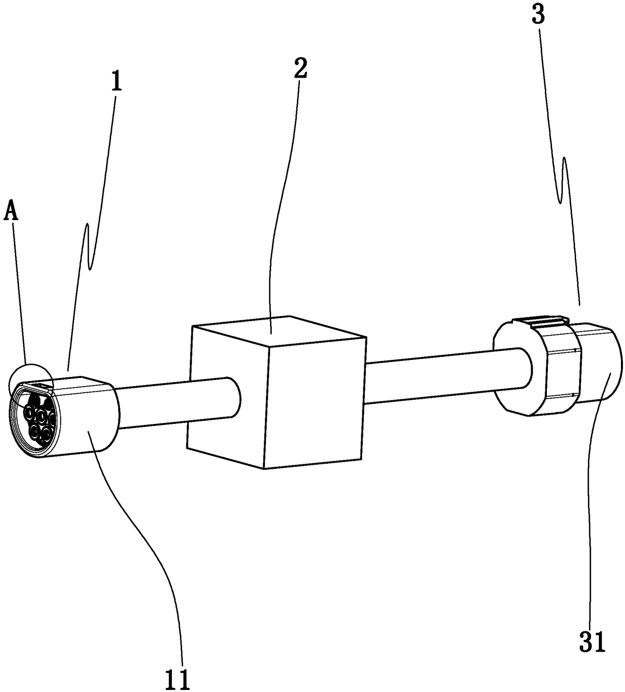
[0029] Example 1: Such as Figure 1 to Figure 3 Shown in, an electric vehicle charging adapter, including

[0030] A charging input terminal 1, a voltage-current converter 2 and a charging output terminal 3. The charging input terminal is electrically connected to the voltage-current converter, and the voltage-current converter is electrically connected to the charging output terminal;

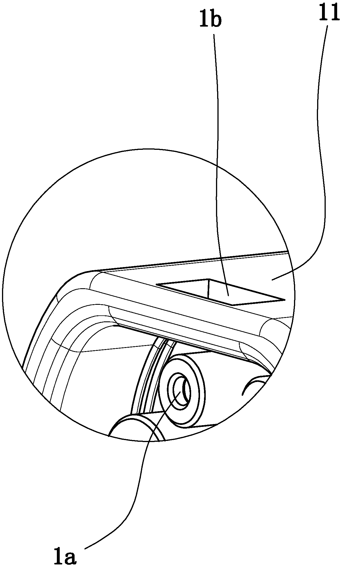
[0031] The charging input terminal includes an input terminal base 11, the input terminal base is provided with an input jack base 1a for docking with a charging gun, and the charging output terminal includes an output terminal base 31, which is provided with a charging socket for docking with an electric vehicle Output jack socket;

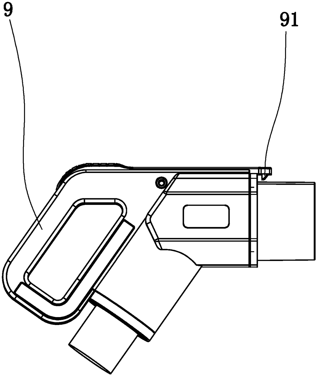
[0032] The input end seat is provided with a card slot 1b for engaging with the chuck 91 on the charging gun 9, and the output end seat is provided with a limit pin for inserting with the pin hole on the electric vehicle.

[0033] The card head is matched with the card s...

Embodiment 2

[0041] Example 2: The basic structure and implementation of this example are the same as Example 1, the difference is that Figure 4 to Figure 7 As shown in the figure, the output end seat is tubular, and the output end seat is provided with an output stop door 33 that is slidably connected to the output end seat and is used to block the output jack seat, and an output stop block 4 used to support the output stop door and A number of output bottom support blocks 5 for contacting the ground, the sliding direction of the output door is up and down, in the vertical direction, the output stop is between the output door and any output bottom support block, and the limit pin is at Below the output block; the input end block is tubular, and the input end block is provided with an input block that is slidably connected to the input block and used to block the input jack block, an input block used to support the input block, and several For the input bottom support block touching the gr...


PUM


Abstract

The invention discloses an electric vehicle charging adapter which comprises a charging input end, a voltage and current converter and a charging output end. The charging input end is electrically connected with the voltage and current converter. The voltage and current converter is electrically connected with the charging output end. The charging input end comprises an input end seat. An input jack seat in butt joint with a charging gun is arranged in the input end seat. The charging output end comprises an output end seat. An output jack seat in butt joint with the charging socket of an electric vehicle is arranged in the output end seat. The input end seat is provided with a clamp slot in clamp joint with a clamp on the charging gun. The output end seat is provided with a stopper pin in insertion joint with a pin hole in the electric vehicle. The electric vehicle charging adapter provided by the invention has the advantages of reasonable structure, effective transfer, wide adaptability, effectively reduced cost, fixed and secure charging, good dustproof and waterproof functions, good protection effect and good charging safety.

Description

Technical field [0001] The invention belongs to the technical field of electric vehicle charging, and particularly relates to an electric vehicle charging adapter and a use method thereof. Background technique [0002] Electric vehicles are favored by governments of various countries due to their environmental protection. The construction of charging stations and the unification of charging standards also make charging of electric vehicles more convenient. However, electric vehicles still make consumers worry about shorter cruising range and longer charging time. Some electric vehicles are only equipped with a slow-charging charging stand, which often requires seven or eight hours of charging time. Some electric vehicles are equipped with both a slow-charging charging stand and a fast-charging charging stand at the same time to meet the needs of consumers for fast and slow charging. [0003] At present, most domestic electric vehicle charging interfaces use GB / T20234.2-2015 recom...

Claims


Application Information

Patent Timeline
Patent Type & Authority Patents(China)
IPC IPC(8): H01R31/06H01R13/52B60L11/18
CPCB60L53/14H01R13/5205H01R13/5219H01R31/06Y02T10/70Y02T10/7072Y02T90/14
Inventor 张友国王爱珍
Owner ZHEJIANG LEAPMOTOR TECH CO LTD
Learn More