

Surgical implant
A surgical implant and implant technology, applied in the field of surgical implants, can solve the problems of poor treatment effect and inconvenient use of implants.
- Summary
- Abstract
- Description
- Claims
- Application Information
AI Technical Summary
Problems solved by technology
Method used
Image

Examples
example 1
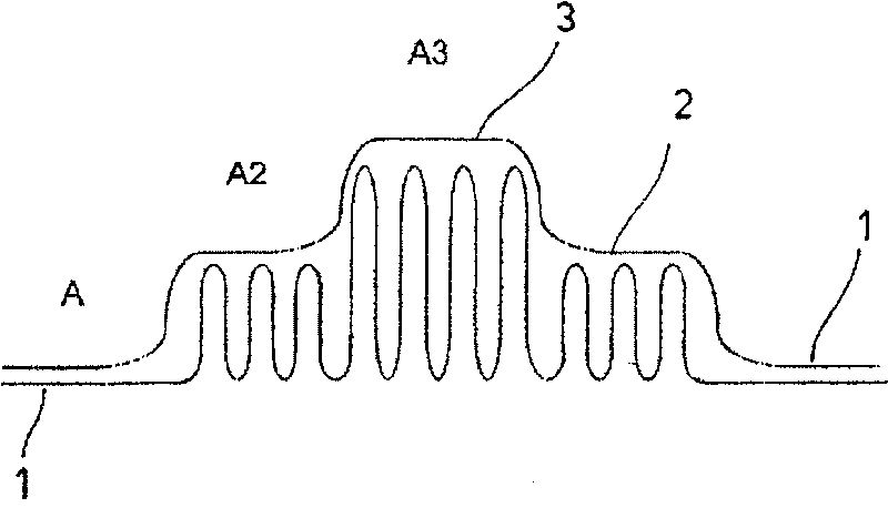
[0030] Fig. 1 is a schematic longitudinal cross-sectional view of an embodiment of a surgical implant with two-stage protrusions that does not match the actual size ratio. Fig. 2 is a top view of this embodiment.
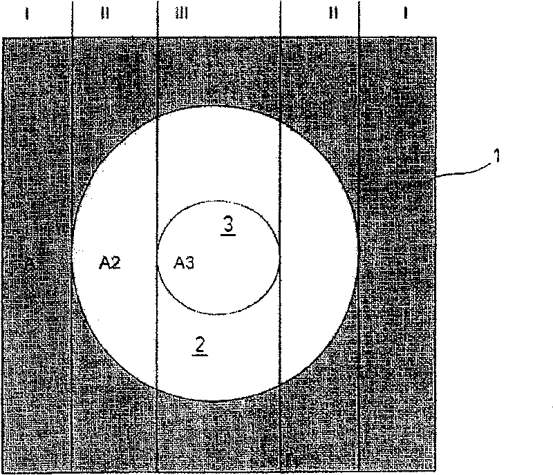
[0031] The implant includes a surface base structure 1, a protrusion 2 and a protrusion 3 whose height (thickness) relative to the plane defined by the top surface of the base structure 1 is higher than the height of the protrusion 2. In the illustrated embodiment, the base structure 1 and the two protrusions 2 and 3 are integrally formed with a shaped loop spacer knitted fabric, which will be described in detail below. 1 and 2, the surface defining the base structure 1 and the protrusions 2 and 3 in a plan view is denoted by A, A2, and A3.
[0032] The formed loop spacer knitted fabric used in this example and the following examples was produced on Mayer's double-needle Raschel knitting machine (with 3-6 needle boards) RD6N. The base structure with different patterns ...
example 2
[0055] Figure 7 It is a schematic diagram of another embodiment of a surgical implant (not to scale). In this example, the surface base structure 10 of the implant is a flexible mesh 12, on which a protrusion 14 in the shape of a champagne bottle stopper made of a shaped loop spacer knitted fabric is connected. The protrusion 14 is divided into two parts, namely, a connecting portion 15 formed by a brim-shaped connecting area 16 carried on the mesh 12 and a frusto-conical middle portion 17, and a widened portion 18 connected separately. The widened part 18 is firmly sewn on the middle part 17.
[0056] In the illustrated embodiment, the mesh 12 is an "Ultrapro" mesh (Ethicon made of absorbable monofilament "Monocryl" (see above) and non-absorbable monofilament "Prolene" (polypropylene; see above) ) The trademark of the synthetic mesh produced), the size of which is about 90mm×150mm, with rounded corners.
[0057] The protrusion 14 in the illustrated embodiment is composed of two...
example 3
[0073] Figure 8 It is a schematic longitudinal sectional view of another embodiment of a surgical implant 20 with filler.
[0074] The base structure 21 of the implant 20 is composed of two layers of partially absorbent knitted fabrics 22, 23, with an absorbable film 24 (used as a bonding device) between the two layers. A suitable material for the layers 22 and 23 is, for example, an "Ultrapro" mesh, but it can also be a mesh with a higher content of "Monocryl" (so that it has good thermoformability and is easy to handle). The layer 23 is thermally deformed into a truncated cone shape, thereby forming a protrusion 26, so a part of the layer 23 belongs to the protrusion 26. The protrusion 26 contains a mixture of absorbable materials with different melting points used as fillers, one part is used to connect with the base structure, and the other part is used as a filler with a certain compressibility and absorbing liquid. The filler 28 is held together by a textile sleeve 29.
...
PUM
 Abstract
Description
Claims
Application Information