Rotor engine

A technology of rotor engines and rotors, which is applied to combustion engines, machines/engines, internal combustion piston engines, etc., and can solve problems such as inability to generate forces in the same direction

Inactive Publication Date: 2008-01-23
陈维加
View PDF2 Cites 0 Cited by
  • Summary
  • Abstract
  • Description
  • Claims
  • Application Information

AI Technical Summary

Problems solved by technology

[0003] Although the scissor structure has a four-stroke process, the force generated after ignition will cause the left and right blades to move in two opposite directions. Although the blades have a certain inertia, the two blades cannot produce the same direction when they act on the same output shaft. Therefore, it is impossible for the left and right blades of the engine to maintain normal rotation in the same direction, and it is also impossible for the kinetic energy generated by fuel to directly change into rotational kinetic energy.

Method used


Image

  • Rotor engine
  • Rotor engine
  • Rotor engine

Examples


Embodiment

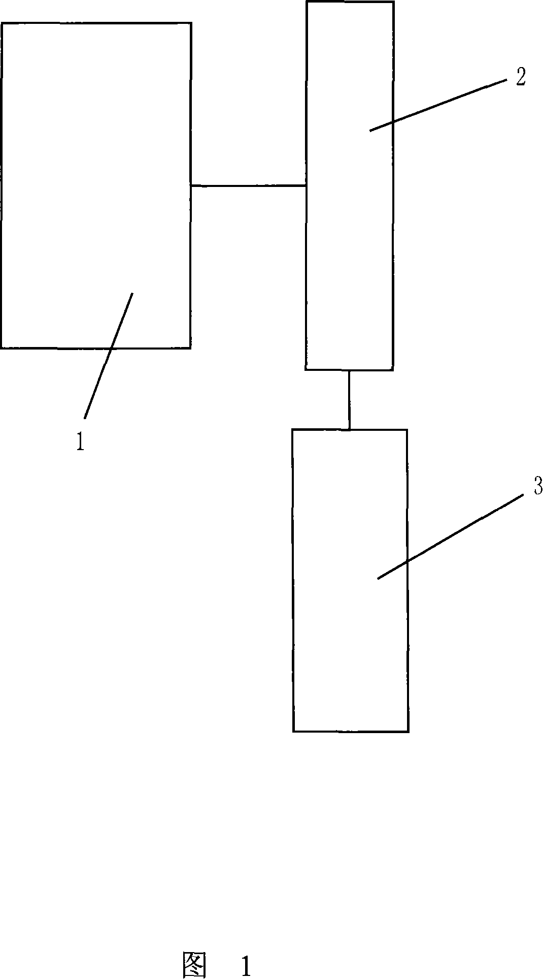
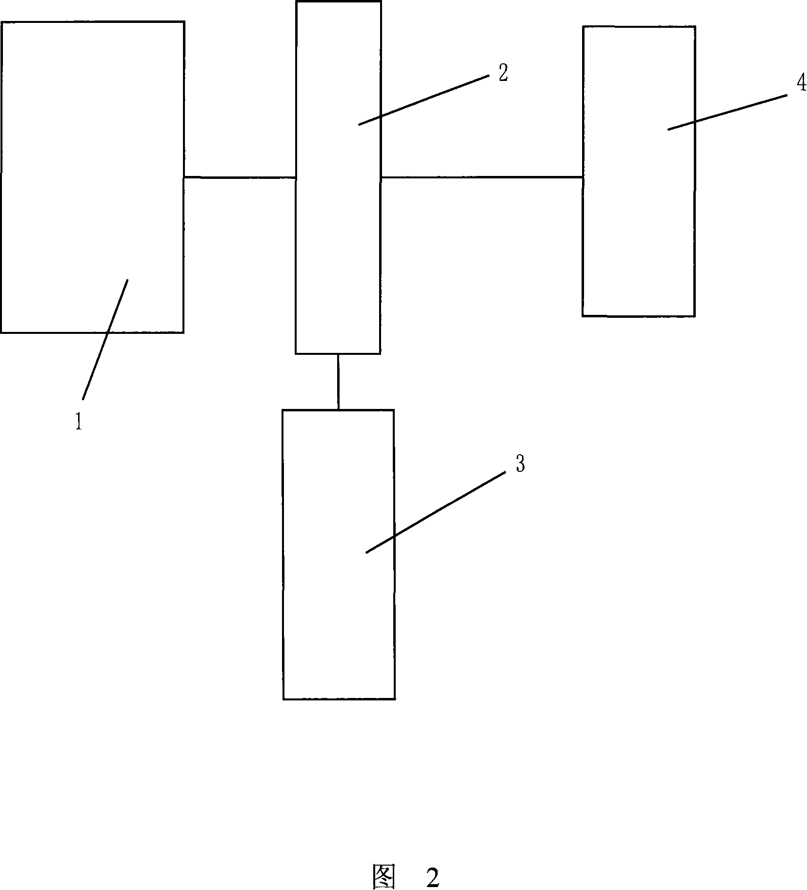
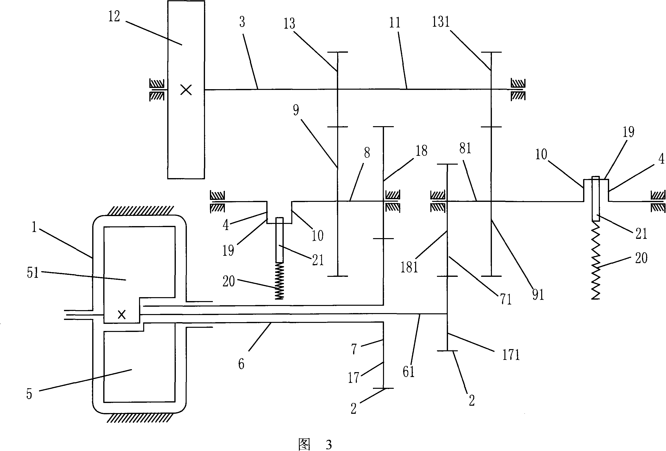
[0023] Embodiment: as shown in Fig. 2 and Fig. 3, a kind of rotary engine comprises rotary engine 1, and the output shafts 6, 61 of two rotors 5, 51 of rotary engine 1 are installed with transmission device 2 respectively, and rotary engine 1 is passed transmission The device 2 is driven by a power take-off 3 and a booster 4 .

[0024] Transmission device 2 comprises the primary gear transmission mechanism 7,71 that is installed on the output shaft 6,61 respectively, and it comprises active elliptical gear 17,171 and passive eccentric gear 18,181, and the major axes of two active elliptical gears 17,171 are opposite Set vertically, when the far point of one of the active oval gears 17 cooperates with the near point of the passive eccentric gear 18 (as shown in Figure 4), the near point of the other active oval gear 171 cooperates with the far point of the passive eccentric gear 181 (as shown in Figure 4). Figure 5).

[0025] The booster device 4 includes rotating parts 10, 10...


PUM


Abstract

The invention discloses a rotor engine, on the output shafts of the two rotors of the engine, a drive is mounted respectively. The rotor engine drives the power outputting device through the drive. The drive comprises a one-stage or multi-stage gear drive mounted respectively on the output shaft. The drive also drives a boosting mechanism, which comprises a rotating part arranged on the last gear shaft of the one-stage or multi-stage gear drive; on the rotating part, an elastic part that can rotate with the rotating part and telescope is connected. The invention allows two rotors to rotate in same direction so as to realize continuous rotation of the rotor engine by offsetting the force in opposite direction received by the back boosting wheel through alternative action of the elastic part.

Description

technical field [0001] The invention relates to a rotary engine. Background technique [0002] Since the 1950s and 1960s, someone has proposed a scissor motion engine in which two rotors placed alternately rotate concentrically with the rotor shaft in a cylindrical cavity, such as US patents 3144007, 3356079, 4068985, 2734489 , Chinese patent 91201678 etc., there are many similar patents published later. But all the inventions in the past have never heard the information of any engine running successfully on this principle. Analyzing these invention patents, it can be seen that almost all inventors revolve around how the scissors structure opens and closes in a certain way, but ignores the most important condition of how to make the scissors structure move continuously, as shown in Figure 1. [0003] Although the scissor structure has a four-stroke process, the force generated after ignition will cause the left and right blades to move in two opposite directions. Although ...

Claims


Application Information

Patent Timeline
Patent Type & Authority Applications(China)
IPC IPC(8): F02B53/12
CPCY02T10/17Y02T10/12
Inventor 陈维加
Owner 陈维加
Why Eureka
Try Eureka