Rotor engine with boosting flywheel

A technology of rotary engine and gear transmission mechanism, applied in the direction of rotary piston engine, rotary or swing piston engine, combustion engine, etc., can solve the problem that the force in the same direction cannot be generated, and achieve the effect of balanced torque energy output

Inactive Publication Date: 2007-10-03
陈维加
View PDF2 Cites 2 Cited by
  • Summary
  • Abstract
  • Description
  • Claims
  • Application Information

AI Technical Summary

Problems solved by technology

[0003] Although the scissor structure has a four-stroke process, the force generated after ignition will cause the left and right blades to move in two opposite directions. Although the blades have a certain inertia, the two blades cannot produce the same direction when they act on the same output shaft. Therefore, it is impossible for the left and right blades of the engine to maintain normal rotation in the same direction, and it is also impossible for the kinetic energy generated by fuel to directly change into rotational kinetic energy.

Method used


Image

  • Rotor engine with boosting flywheel
  • Rotor engine with boosting flywheel
  • Rotor engine with boosting flywheel

Examples


Embodiment 1

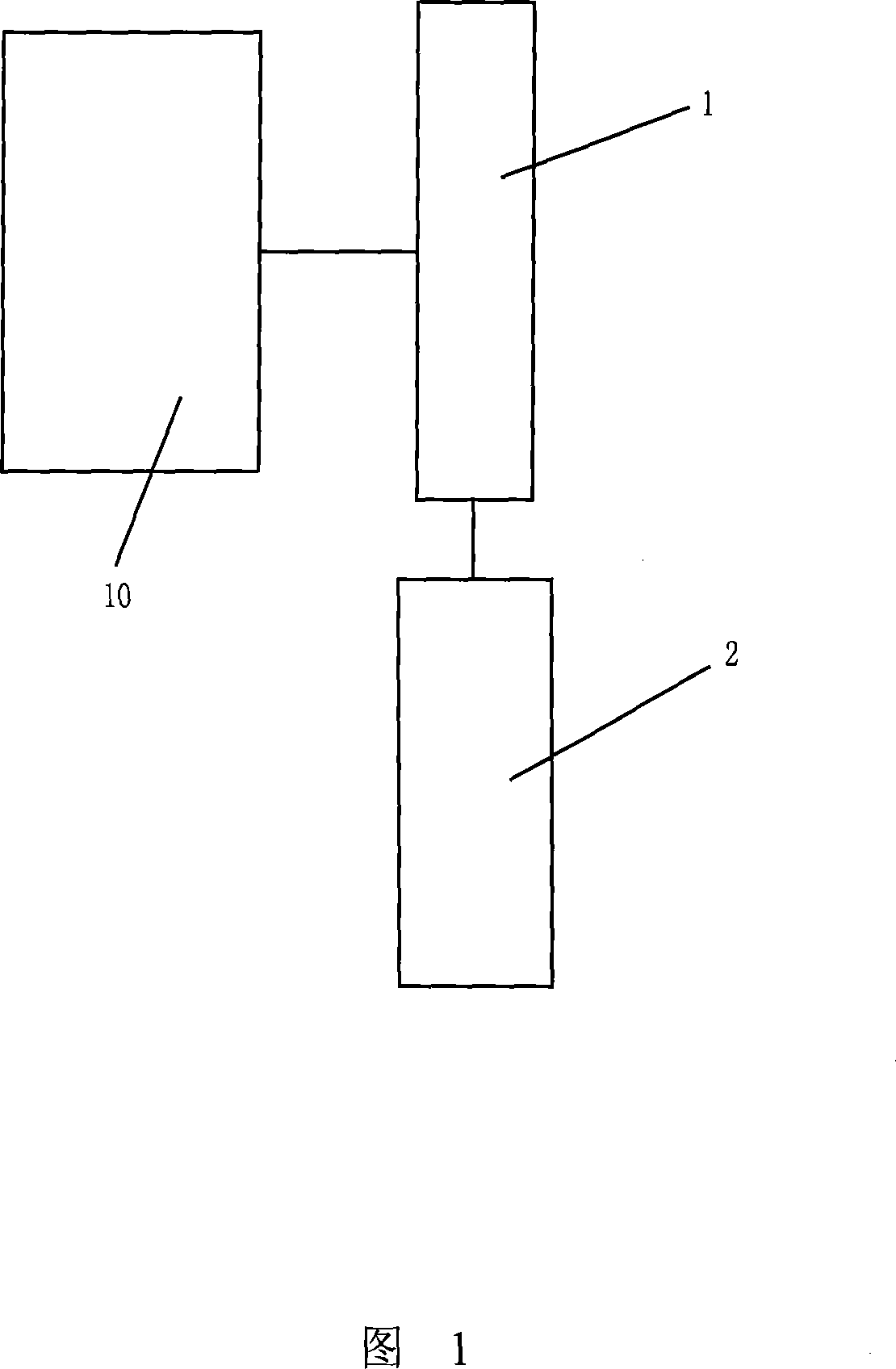
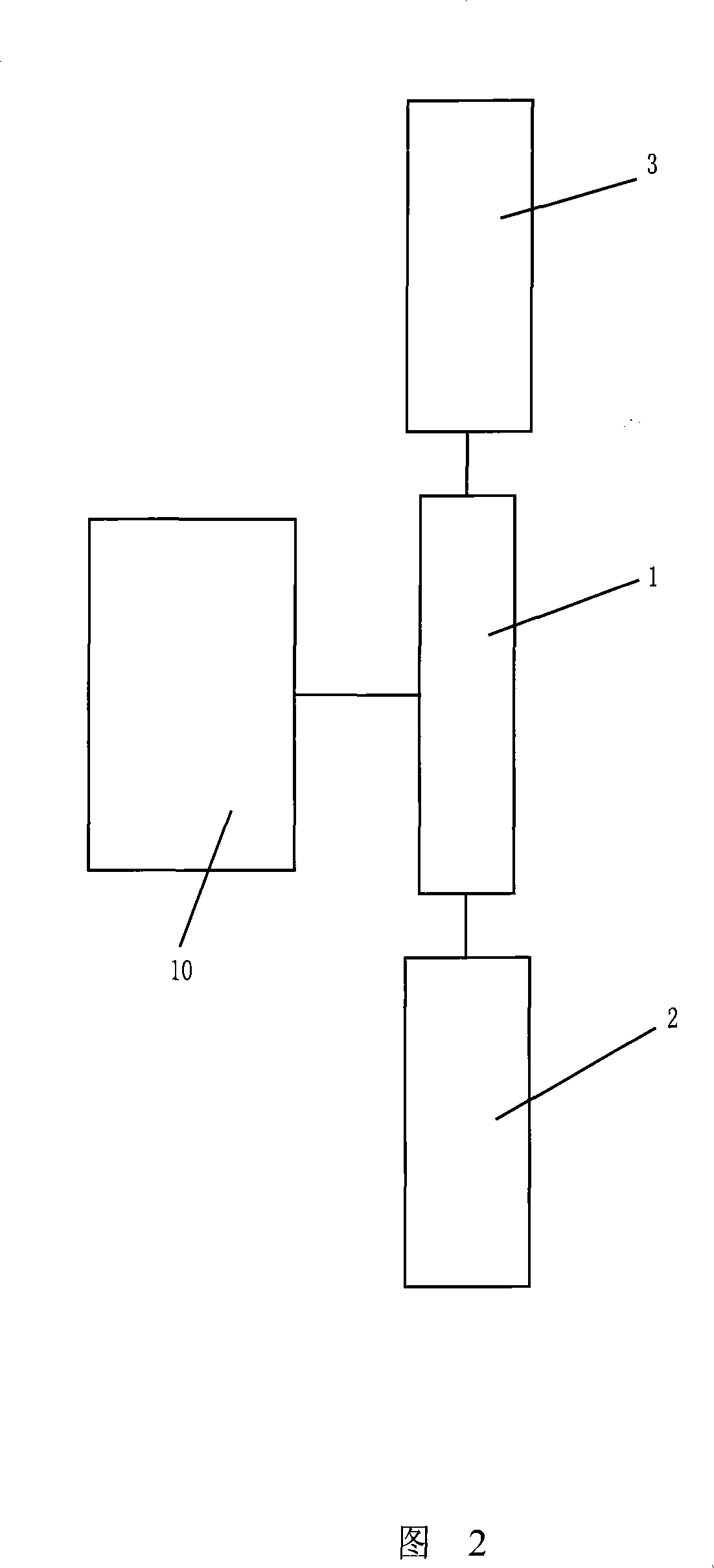
[0019] Embodiment 1: As shown in Figures 2 and 4, a rotary engine with a booster flywheel includes a rotary engine 10, and a transmission 1 is installed on the output shafts 5 and 51 of the two rotors 4 and 41 of the rotary engine, respectively. , the transmission device 1 includes a driving gear 81, two driven gears 82 meshing with the driving gear 81 respectively, and the two driven gears 82 drive the booster device 3 and the power output device 2 respectively; the booster device 3 is the booster flywheels 6 and 61, The booster flywheels 6 and 61 are arranged on the passive transmission shafts 7 and 71 ; the other two passive transmission shafts 72 and 73 of the two transmission devices 1 are arranged coaxially and are provided with an output flywheel 9 coaxially.

Embodiment 2

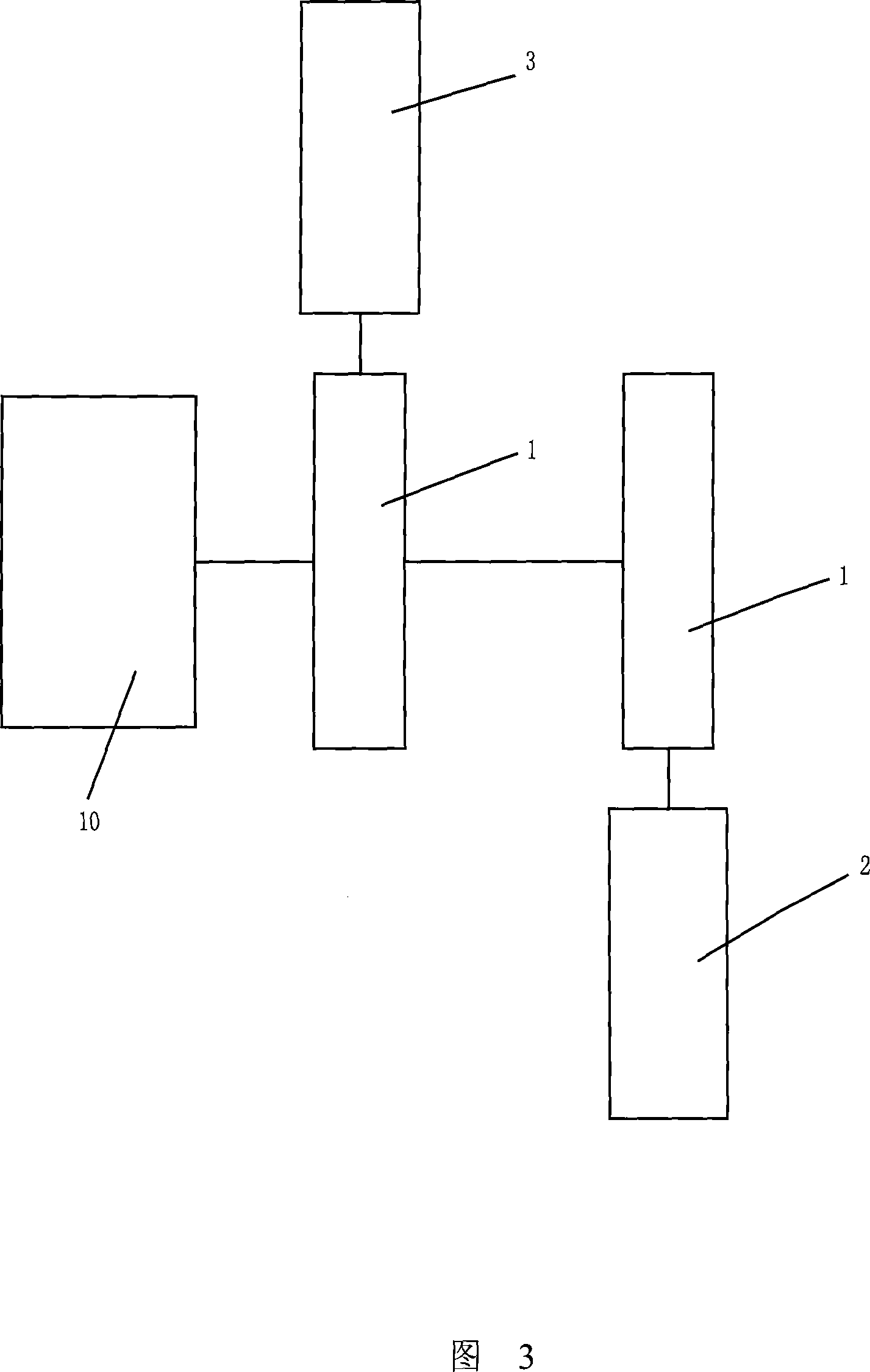
[0020] Embodiment 2: As shown in Figures 3 and 5, a rotary engine with a booster flywheel includes a rotary engine 10, and a transmission 1 is installed on the output shafts 5 and 51 of the two rotors 4 and 41 of the rotary engine, respectively. , the transmission device 1 comprises two coaxial first-stage gear transmission mechanisms 83 and 84 respectively, and the two groups of coaxial first-stage gear transmission mechanisms 83 and 84 drive the booster device 3 and the power output device 2 respectively; the booster device 3 is The booster flywheels 6 and 61 are arranged on the corresponding passive transmission shafts 7 and 71; the other two passive transmission shafts 72 and 73 of the two transmission devices 1 are arranged coaxially and are coaxially provided with an output flywheel 9 .

[0021] The above-mentioned transmission device 1 can also be a multi-stage gear transmission mechanism, and the booster flywheels 6 and 61 are arranged on the last-stage transmission sh...


PUM


Abstract

The rotor engine with boosting flywheel includes one rotor engine, one driving device for the rotor engine to drive one power output device, and one boosting device driven by the rotor engine. The present invention adopts flywheel to counteract the resistance to the back assisting wheel alternately for the two rotors to rotate in the same direction, so as to realize the lasting rotation of the rotor engine.

Description

technical field [0001] The invention relates to a rotary engine with a booster flywheel. Background technique [0002] Since the 1950s and 1960s, some people have proposed a scissor motion engine in which two mutually intersecting rotors rotate concentrically with the rotor shaft in a cylindrical cavity. , Chinese patent 91201678, etc. Many similar patents have been published in the future. But none of the previous inventions have ever heard of a single engine operating successfully on this principle. Analyzing these invention patents, it can be seen that almost all inventors focus on how to open and close the scissors structure in a certain way, but ignore the most important condition of how to make the scissors structure move continuously, as shown in Figure 1. [0003] Although the scissors structure has a four-stroke process, the force generated after ignition will cause the left and right blades to move in two opposite directions. Although the blades have a certain in...

Claims


Application Information

Patent Timeline
Patent Type & Authority Applications(China)
IPC IPC(8): F01C1/063F02B53/14
CPCF01C1/063
Inventor 陈维加
Owner 陈维加
Why Eureka
Try Eureka