Rotor engine

A rotary engine, rotor technology, applied in combustion engines, machines/engines, internal combustion piston engines, etc., to achieve the effect of balancing energy output and balancing torque

Inactive Publication Date: 2009-03-18
陈维加
View PDF8 Cites 0 Cited by
  • Summary
  • Abstract
  • Description
  • Claims
  • Application Information

AI Technical Summary

Problems solved by technology

[0004] Although this patent has a four-stroke process, the force generated after ignition will cause the left and right blades to move in two opposite directions. Although the blades have a certain inertia, they still cannot counteract the force in the opposite direction. 1. It is impossible for the right blade to maintain normal rotation in the same direction, and it is impossible to directly convert the kinetic energy generated by fuel into rotational kinetic energy

Method used


Image

  • Rotor engine
  • Rotor engine
  • Rotor engine

Examples


Embodiment

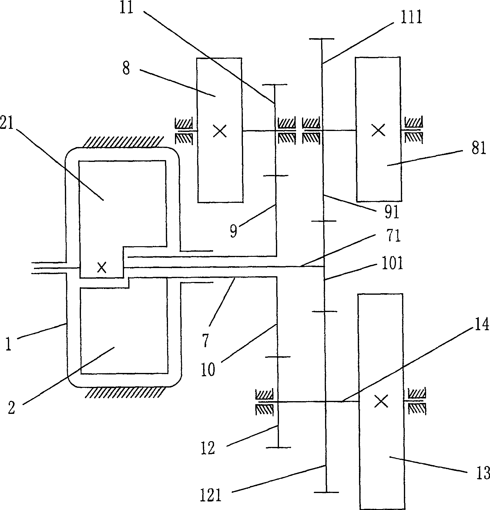
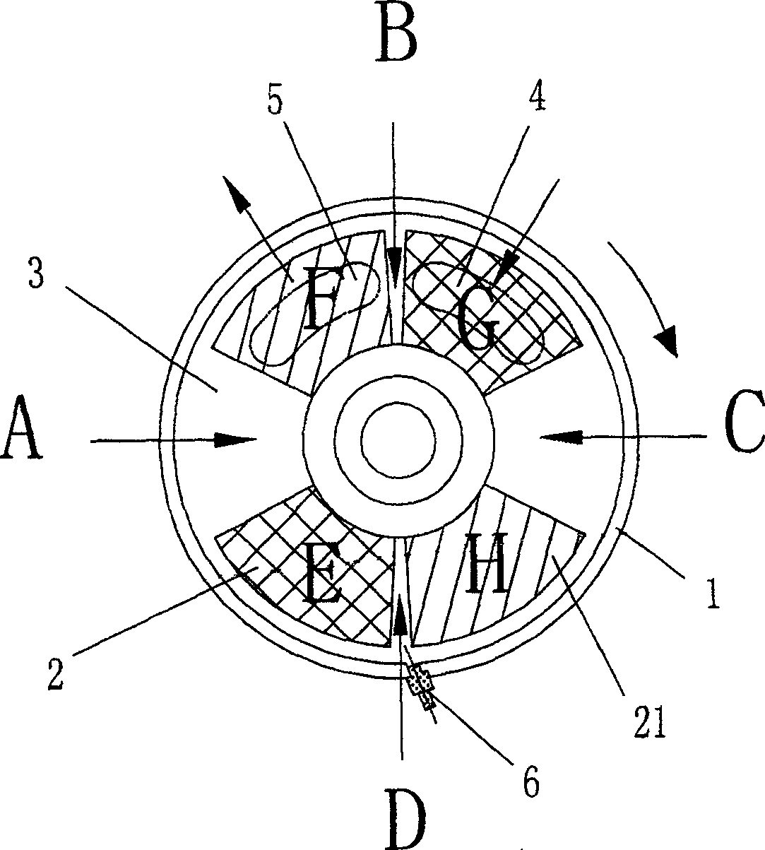
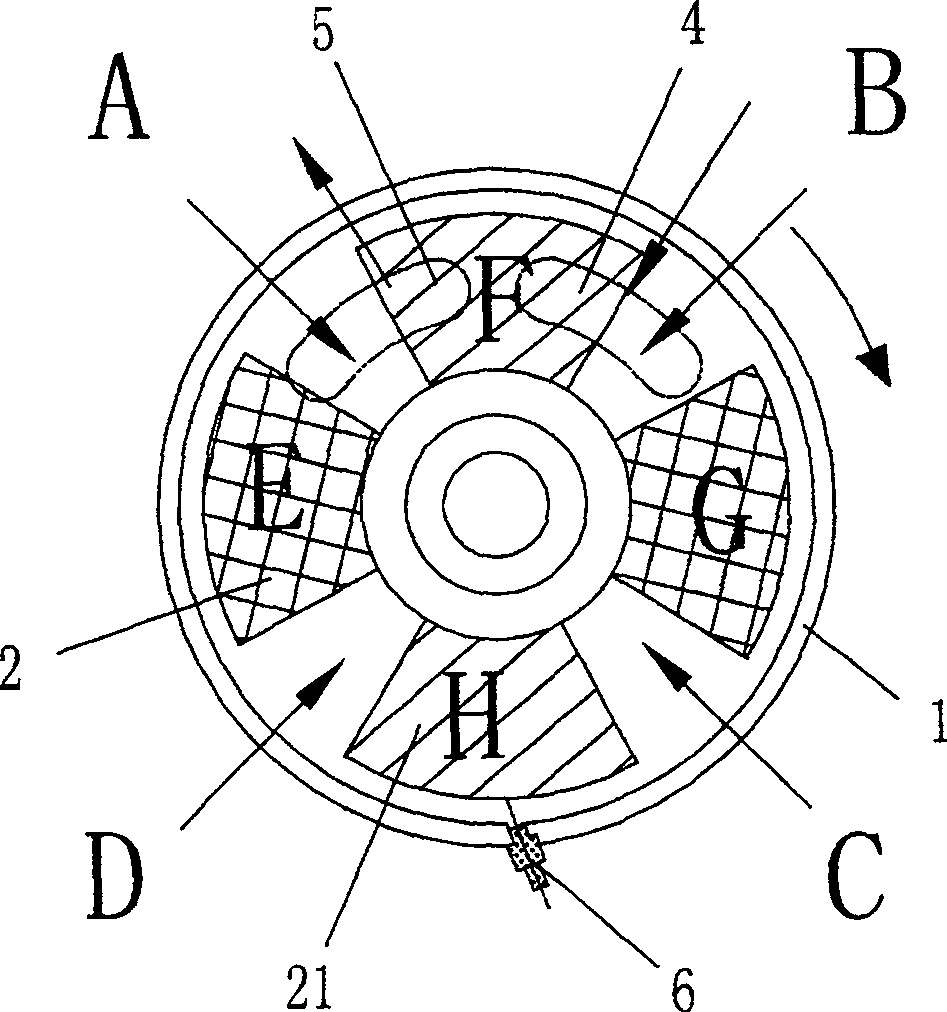
[0016] Example: such as figure 1 As shown, a rotary engine includes a cylinder block 1, and two vane rotors 2 and 21 are arranged in the cylinder block 1, and the two rotors 2 and 21 and the cylinder block 1 form at least four sealed chambers 3 through elastic sealing sheets , Cylinder block 1 is provided with intake port 4, exhaust port 5 and ignition or nozzle device 6, rotor output shaft 7 and 71 of two rotors 2 and 21 is connected with rotor flywheel 8 and 81 through speed change device 9 and 91.

[0017] Speed ​​change devices 9 and 91 include rotor oval gears 10 and 101 fixed on rotor output shafts 7 and 71, rotor flywheel oval gears 11 and 111 meshed with rotor oval gears 10 and 101, rotor flywheels 8 and 81 and rotor flywheel oval gears 11 and 111 are coaxially fixed respectively, and the two rotor oval gears 10 and 101 are respectively meshed with output flywheel oval gears 12 and 121, and the two output flywheel oval gears 12 and 121 are arranged on the engine output...


PUM


Abstract

The invention discloses a rotary expansion engine. It contains cylinder body with two vane rotors inside. The rotors together with the cylinder body form at least four canned cavities through elastic sealing strips. The cylinder body has air intake, air vent, firing device or nozzle. Flywheels are set on output axis of two rotors separately. The invention uses inertia of rotor flywheels to buck force toward reverse direction of back aiding wheel, which realizes the synthetic continuous rotation of the two rotors. Change angles of the two impellers regularly and transfer kinetic energy produced by fuel oil to rotary kinetic energy by using speed variator. It works external with output flywheels.

Description

technical field [0001] The invention relates to a rotary engine. Background technique [0002] The currently used fuel engines are all crankshaft-connecting rod mechanism type. The efficiency of this engine is low, and when the mechanism is at the top dead center, the cylinder pressure is the highest, but the conversion efficiency is the lowest, which is zero. Then it is restricted by the ratio of the radius of the crankshaft to the connecting rod, and the efficiency is not ideal. [0003] In order to overcome the above defects, some people have applied for an improved engine, such as the utility model patent No. "200420006372.7" and the name "blade engine" announced by the State Intellectual Property Office on September 28, 2005. The left and right blades are placed on the engine shaft in the cylinder body. The left and right blades cooperate with the cylinder body to form four chambers. The left large cylindrical gear is fixed on the left blade, and the left small cylindr...

Claims


Application Information

Patent Timeline
Patent Type & Authority Patents(China)
IPC IPC(8): F02B53/00
CPCY02T10/17Y02T10/12
Inventor 陈维加
Owner 陈维加
Why Eureka
Try Eureka