Rotor engine with magnetic boosting
A rotary engine, boosting technology, applied in the direction of rotary piston engine, rotary or oscillating piston engine, combustion engine, etc., can solve the problems of large noise and vibration, inability to generate force in the same direction, etc., to reduce vibration and noise, Balanced torque, smooth rotation effect
- Summary
- Abstract
- Description
- Claims
- Application Information
AI Technical Summary
Problems solved by technology
Method used
Image
Examples
Embodiment 1
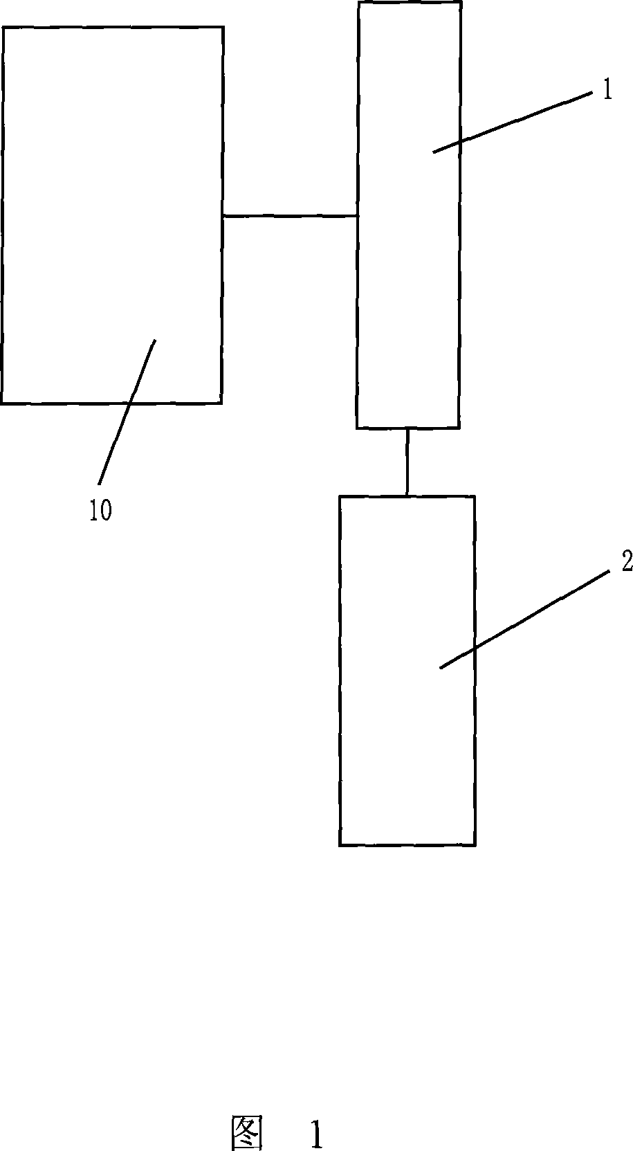
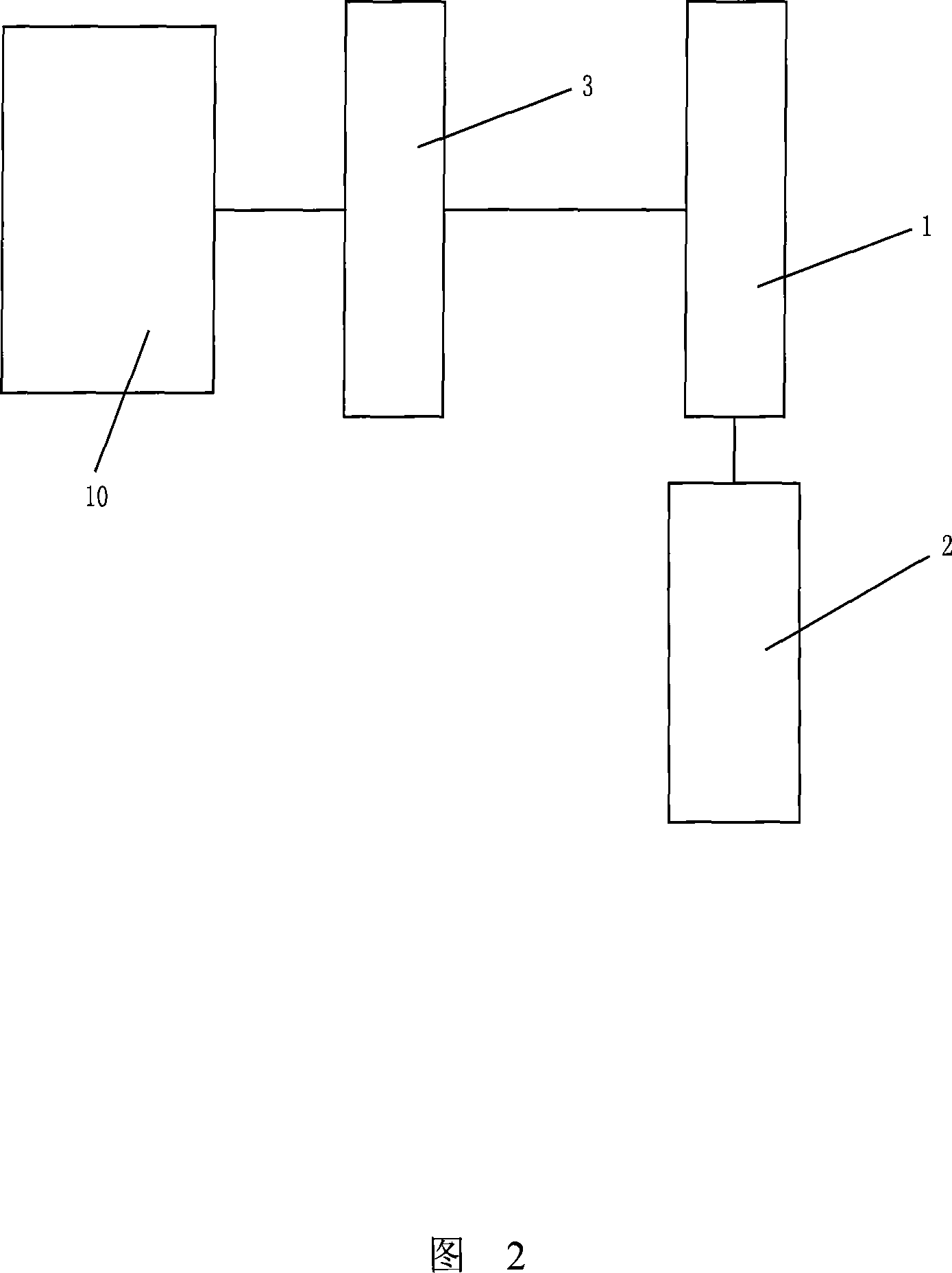
[0025] Embodiment 1: As shown in Fig. 2 and Fig. 5, a rotary motor with magnetic force boosting includes a rotary motor 10, the rotary motor 10 drives a power output device 2 through a transmission device 1, and the two rotors 4 of the rotary motor 10 The output shafts 5 and 51 of 41 and 41 are respectively equipped with a transmission device 1 and a booster device 3. The booster device 3 includes a booster flywheel 6, an induction wheel 14 connected inductively with the booster flywheel 6, and the induction wheel 14 is arranged on the rotor. On the output shaft; the transmission device 1 is a one-stage or multi-stage gear transmission mechanism, and the last-stage passive transmission shaft 71 of the two transmission devices 1 is coaxially arranged and an output flywheel 9 is coaxially provided.
Embodiment 2
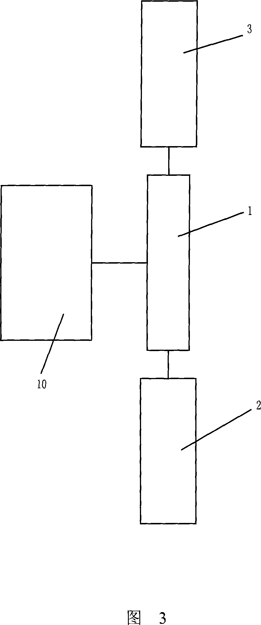
[0026] Embodiment 2: As shown in Fig. 3 and Fig. 6, a rotary motor with magnetic force boosting includes a rotary motor 10, and a transmission device 1 is respectively installed on the output shafts 5 and 51 of the two rotors 4 and 41 of the rotary motor , the transmission device 1 includes a driving gear 81, two driven gears 82 meshing with the driving gear 81 respectively, and the two driven gears 82 drive the booster device 3 and the power take-off device 2 respectively; the booster device 3 includes a booster flywheel 6, and a booster The induction wheel 14 that pushes the flywheel 6 is inductively connected, and the induction wheel 14 is arranged on the last stage of the passive transmission shaft 7 of the transmission device 1; one of the induction wheel 14 and the booster flywheel 6 is a magnetic body, and the other is a magnetizer, and the induction wheel 14 and the booster flywheel 6 are connected by magnetic induction; the other two driven transmission shafts 71 of th...
Embodiment 3
[0027] Embodiment 3: As shown in Fig. 4 and Fig. 7, a rotary motor with magnetic boosting includes a rotary motor 10, and a transmission device 1 is respectively installed on the output shafts 5 and 51 of the two rotors 4 and 41 of the rotary motor , the transmission device 1 includes two sets of coaxial first-stage gear transmission mechanisms 83 and 84 respectively, and the two sets of coaxial first-stage gear transmission mechanisms 83 and 84 respectively drive the booster device 3 and the power take-off device 2; the booster device 3 includes The booster flywheel 6, the induction wheel 14 connected inductively with the booster flywheel 6, the induction wheel 14 is arranged on the last stage passive transmission shaft 7 of the transmission device 1; one of the induction wheel 14 and the booster flywheel 6 is a magnetic body, and the other One is a magnet guide, and the induction wheel 14 and the booster flywheel 6 are magnetically connected; the other two driven transmission...
PUM
 Abstract
Description
Claims
Application Information
 - R&D
- Intellectual Property
- Life Sciences
- Materials
- Tech Scout
- Unparalleled Data Quality
- Higher Quality Content
- 60% Fewer Hallucinations
Browse by: Latest US Patents, China's latest patents, Technical Efficacy Thesaurus, Application Domain, Technology Topic, Popular Technical Reports.
© 2025 PatSnap. All rights reserved.Legal|Privacy policy|Modern Slavery Act Transparency Statement|Sitemap|About US| Contact US: help@patsnap.com


