
Light source device and projector

A technology of light source device and lighting device, which is applied in the direction of light source, electric light source, projection device, etc., to achieve the effect of suppressing the decrease of electrode temperature, suppressing flicker, and preventing loss

Inactive Publication Date: 2008-01-30
SEIKO EPSON CORP
View PDF1 Cites 32 Cited by
  • Summary
  • Abstract
  • Description
  • Claims
  • Application Information

AI Technical Summary

Problems solved by technology

[0009] That is, in the technology described in Patent Document 1, since relatively high-frequency low-frequency rectangular wave current and high-frequency rectangular wave current are supplied to the high-pressure discharge lamp, the temperature distribution on the electrode surface becomes uniform, and the first electrode is easily formed. 2 protrusions, as a result, flickering occurs

Method used


Image

  • Light source device and projector
  • Light source device and projector
  • Light source device and projector

Examples


no. 1 Embodiment approach ”

[0040] Hereinafter, a first embodiment of the present invention will be described based on the drawings.

[0041] "Outline Configuration of a Projector"

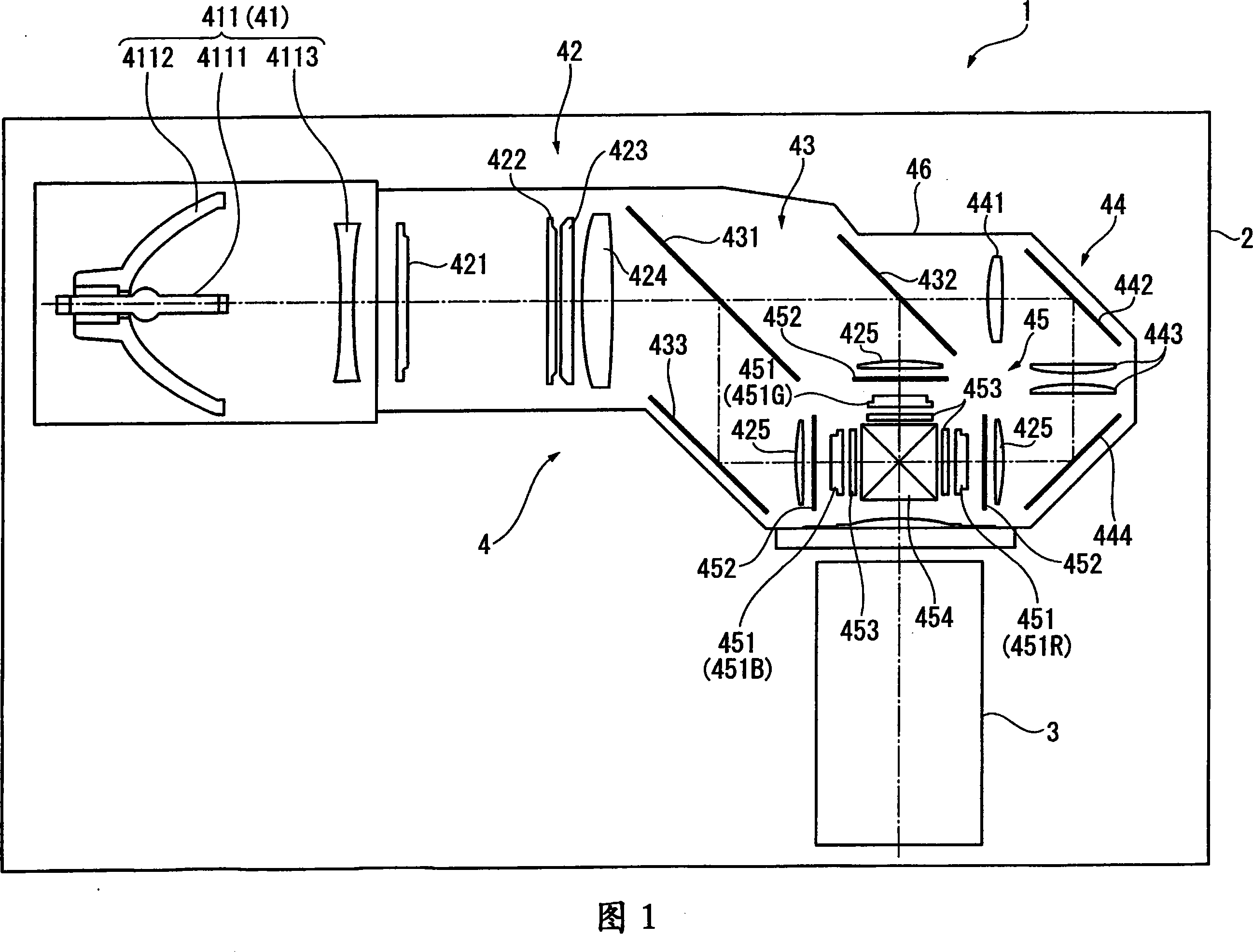
[0042] FIG. 1 is a diagram schematically showing a schematic configuration of a projector 1 .

[0043] The projector 1 modulates light beams emitted from a light source according to image information to form a color image (optical image), and enlarges and projects the color image on a screen (not shown). This projector 1, as shown in FIG. 1, includes a substantially cuboid-shaped exterior case 2, a projection lens 3 as projection optical means, an optical unit 4, and the like.

[0044] In addition, in FIG. 1 , although specific illustrations are omitted, in the outer casing 2, in a space other than the projection lens 3 and the optical unit 4, a cooling unit for cooling the inside of the projector 1 is arranged, A power supply unit that supplies electric power to each component inside the projector 1 , a control board that c...

no. 2 Embodiment approach ”

[0095] Next, a second embodiment of the present invention will be described based on the drawings.

[0096] In the following description, the same structure and the same member as those of the first embodiment described above will be assigned the same reference numerals, and detailed description thereof will be omitted or simplified.

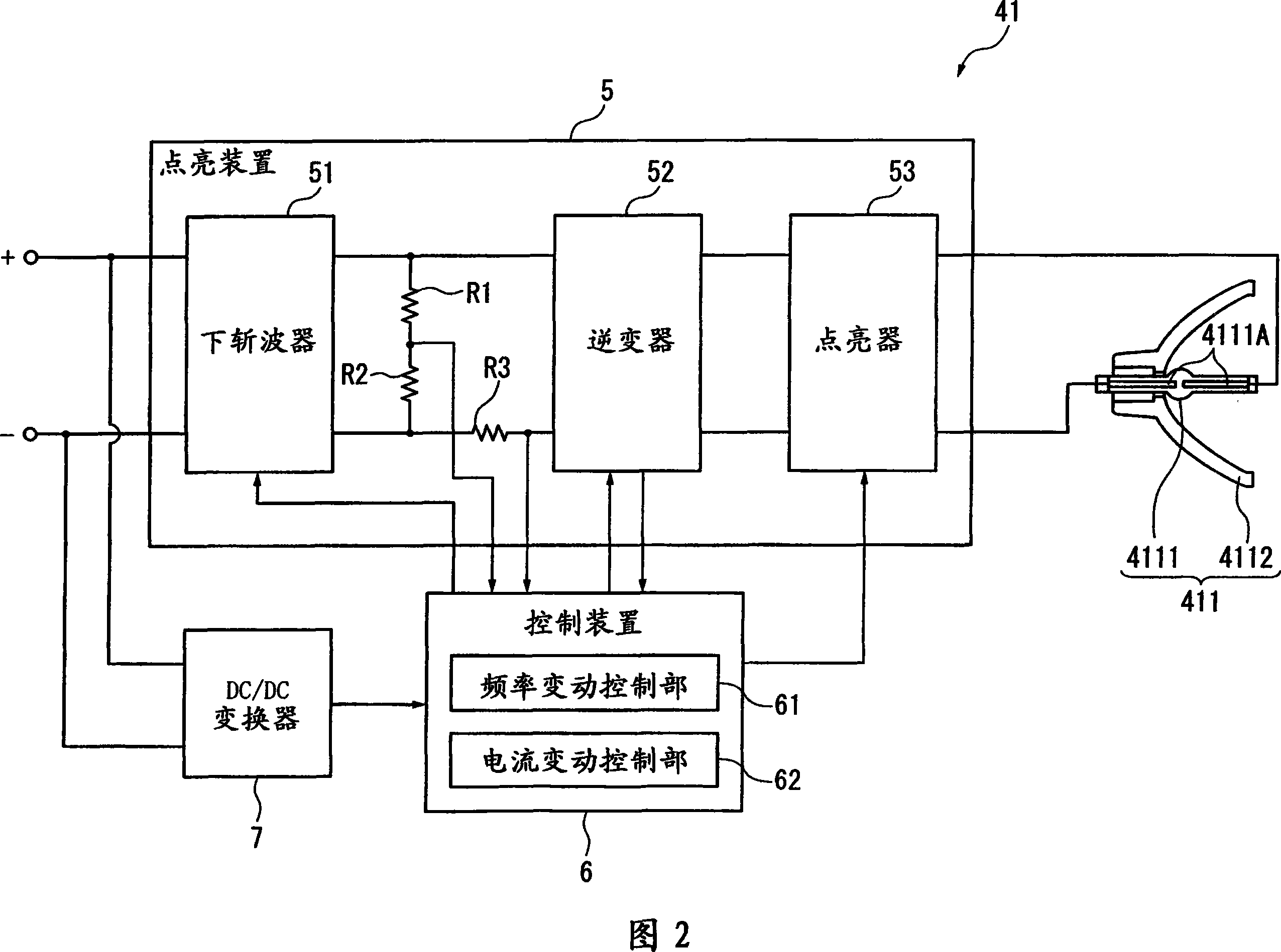
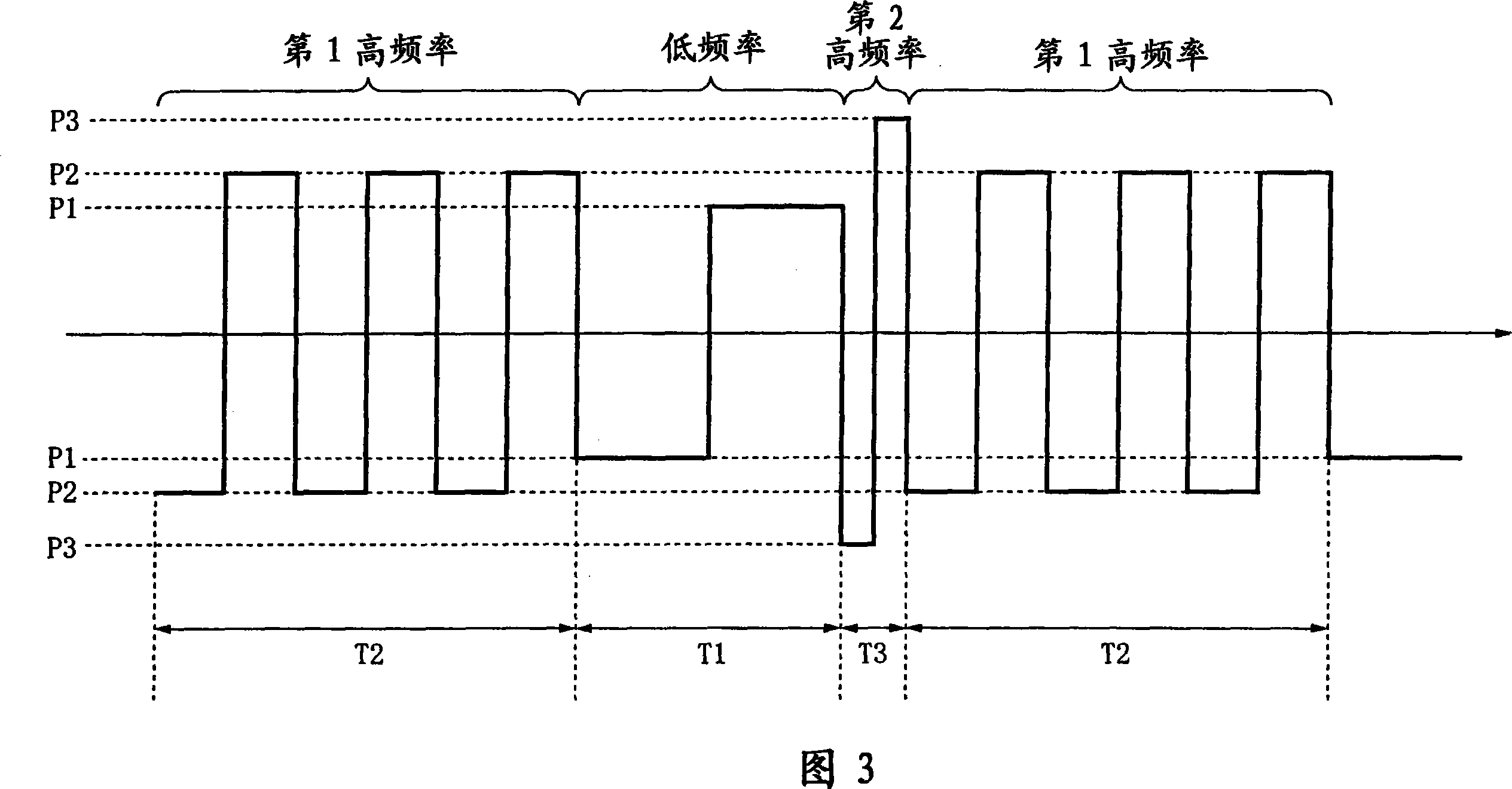
[0097] In the above-mentioned first embodiment, the frequency variation control unit 61 supplies the driving currents of the low frequency, the first high frequency, and the second high frequency to the light source lamp in periods T1, T2, and T3, respectively, when performing the frequency variation control. 4111.

[0098] On the other hand, in the second embodiment, when the frequency variation control unit 61 executes the frequency variation control, immediately before the polarity inversion of every half cycle of the low-frequency drive current waveform, the first high-frequency drive current And the driving current of the second high frequ...


PUM


Abstract

A light source device includes a high-pressure discharge lamp for performing electric discharge emission between a pair of electrodes, a lighting device for lighting the high-pressure discharge lamp by supplying a driving current of a predetermined frequency to the high-pressure discharge lamp, and a control device for controlling the lighting device, wherein the control device controls the frequency of the driving current supplied to the high-pressure discharge lamp from the lighting device and includes a frequency variance controlling section which supplies a low-frequency driving current having a low frequency and two or more types of high-frequency driving currents having frequencies higher than the low frequency to the high-pressure discharge lamp.

Description

technical field [0001] The present invention relates to a light source device and a projector. Background technique [0002] Conventionally, it is known to include: a high-pressure discharge lamp that discharges between a pair of electrodes, a lighting device that supplies a driving current (alternating current) to the high-pressure discharge lamp to drive the high-pressure discharge lamp to light, and a lighting device that controls the high-pressure discharge lamp. The light source device of the control device of the drive control. [0003] In such a light source device, if the high-pressure discharge lamp is turned on with a relatively low frequency (for example, less than 60 Hz) driving current, a protrusion (hereinafter referred to as as the first protrusion). In addition, according to such lighting driving, wear of the electrode tip of the high-pressure discharge lamp can be prevented, and life extension of the high-pressure discharge lamp can be achieved. [0004] ...

Claims


Application Information

Patent Timeline
Patent Type & Authority Applications(China)
IPC IPC(8): G03B21/20G03B21/00H05B41/14H05B41/00
CPCY02B20/208H05B41/2928H05B41/2883Y02B20/00
Inventor 田中和裕牛山富芳
Owner SEIKO EPSON CORP
Learn More