
Gravity cyclotron engine

A technology of engine and rotation, applied in the direction of engines, machines/engines, mechanisms that generate mechanical power, etc., can solve the problems of continuous work, difficulty in gravity, etc., achieve the effects of reducing impact, strengthening rotation, and realizing power expansion

Inactive Publication Date: 2008-02-13
孟武
View PDF3 Cites 4 Cited by
  • Summary
  • Abstract
  • Description
  • Claims
  • Application Information

AI Technical Summary

Problems solved by technology

[0003] Among the many designs mentioned above, they are only negatively decomposing a part of the gravity, trying to make it a driving force for advancement, so they cannot become an anti-gravity equivalent to the gravity of the heavy object itself, so it is difficult to make the gravity continue to work

Method used


Image

  • Gravity cyclotron engine
  • Gravity cyclotron engine
  • Gravity cyclotron engine

Examples


Embodiment Construction

[0045] The present invention is described in detail below in conjunction with accompanying drawing:

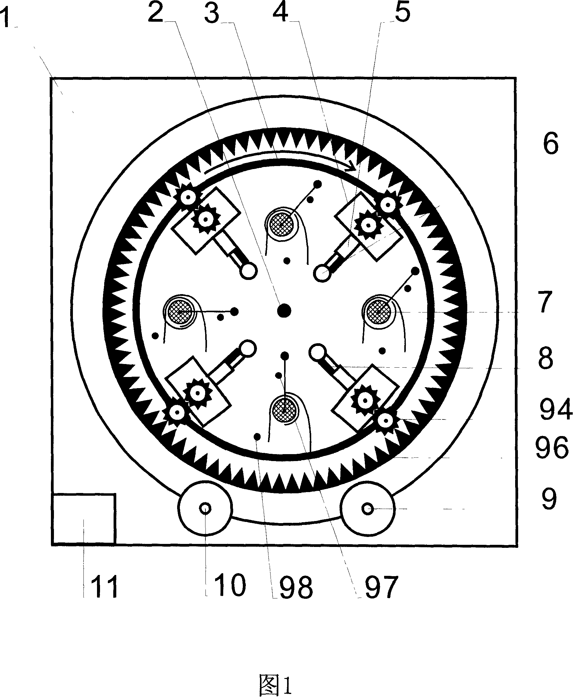
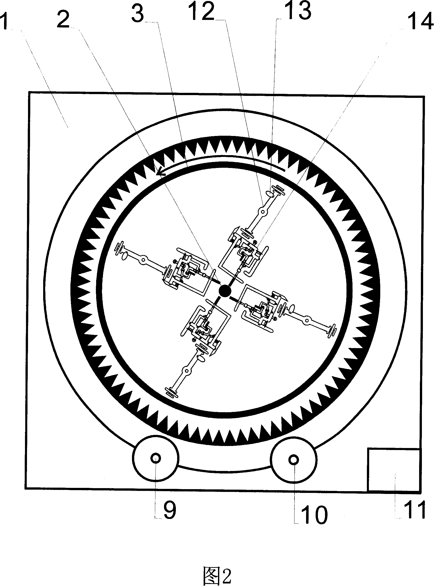
[0046] See Figures 1 and 2. The inner surface of a steel bracket 1 is processed into an internal gear to form an external gear ring 96, and a 4 cm thick steel plate is processed into a disc with a diameter of 2.5 meters in the inside of the external gear ring 96 to be a gravity disc 3, and the gravity disc 3 and The gap between the outer ring gear 96 is 2 cm, and the center of the gravity disc 3 is fixed on the output shaft 2 with a diameter of 5 cm and a length of 50 cm. The output shaft 2 supports the gravity disc 3 on the support 1 through two bearings. Starter 10 and accumulator 11 are arranged on the lower left side, generator 9 is arranged on the lower right side of support 1, and are connected with output shaft 2 with a belt respectively. The structure of starter 10 is the same as the existing starter of the automobile. separate. After the normal operation of the engi...


PUM


Abstract

The invention provides a gravity gyration engine, which uses the gravity gyration to do work and realize an anti-gravity system. The invention is characterized in that at least a gravity plate is fixed on an output shaft, which interacts with a start motor and a power generator; at least two pairs of anti-gravity drives are fixed on the gravity plate with the output shaft as the center; as a working hammer does work twice and make a drive wheel rotate in the same direction within the time the hammer rotates at the gravity plate for a circle, and an anti-gravity hammer, a contraction hammer, and a gyration hammer move to an end near the shaft when they are at the ascending side of the gravity plate, and move to an end far from the shaft when they are at the descending side of the gravity plate, the gravity plate will rotate continuously; the invention is widely applicable in a field related to an engine.

Description

Technical field [0001] The invention relates to an engine, in particular to a gravity gyratory engine which implements an anti-gravity mechanism by gyrating heavy objects. technical background [0002] As we all know, the key to whether gravity can continue to do work is to establish a stable anti-gravity system. The Chinese invention patent "Gravity Unbalanced Device--Perpetual Motion Machine" published on October 29, 1997 (patent application number 96112631.0) has a structure that the inner gear ring decomposes the gravity of the cargo into two unequal components and acts on the outer gear On the ring, the external gear ring turns the two unequal force components to a 90-degree angle through the rolling of the wheel, and becomes a force parallel to the earth's surface, pushing the goods forward; published in China on August 13, 2003 Invention patent "gravity crank perpetual motion machine" (patent application number 02102260.7) has a structural feature that the cylinder b...

Claims


Application Information

Patent Timeline
Patent Type & Authority Applications(China)
IPC IPC(8): F03G7/10F03G3/00
Inventor 孟武
Owner 孟武
Learn More