Connector

A technology of connectors and retainers, which is applied in the direction of the base/housing, etc., can solve the problems of detachment of the mounting part of the rear retainer, separation of the interlocking part and the locking piece, etc., and achieve the effect of improving reliability and suppressing shaking

Inactive Publication Date: 2008-02-13
SUMITOMO WIRING SYST LTD
View PDF0 Cites 25 Cited by
  • Summary
  • Abstract
  • Description
  • Claims
  • Application Information

AI Technical Summary

Problems solved by technology

[0005] If the inner surface of the wire insertion hole of the rear retainer is pressed by the wire when the wire is shaken in a direction intersecting the longitudinal direction, it may cause the interlocking portion and the locking piece to separate due to the generated pressing force, thereby Causes the rear retainer to disengage from the mounting section

Method used


Image

  • Connector
  • Connector
  • Connector

Examples


no. 1 example

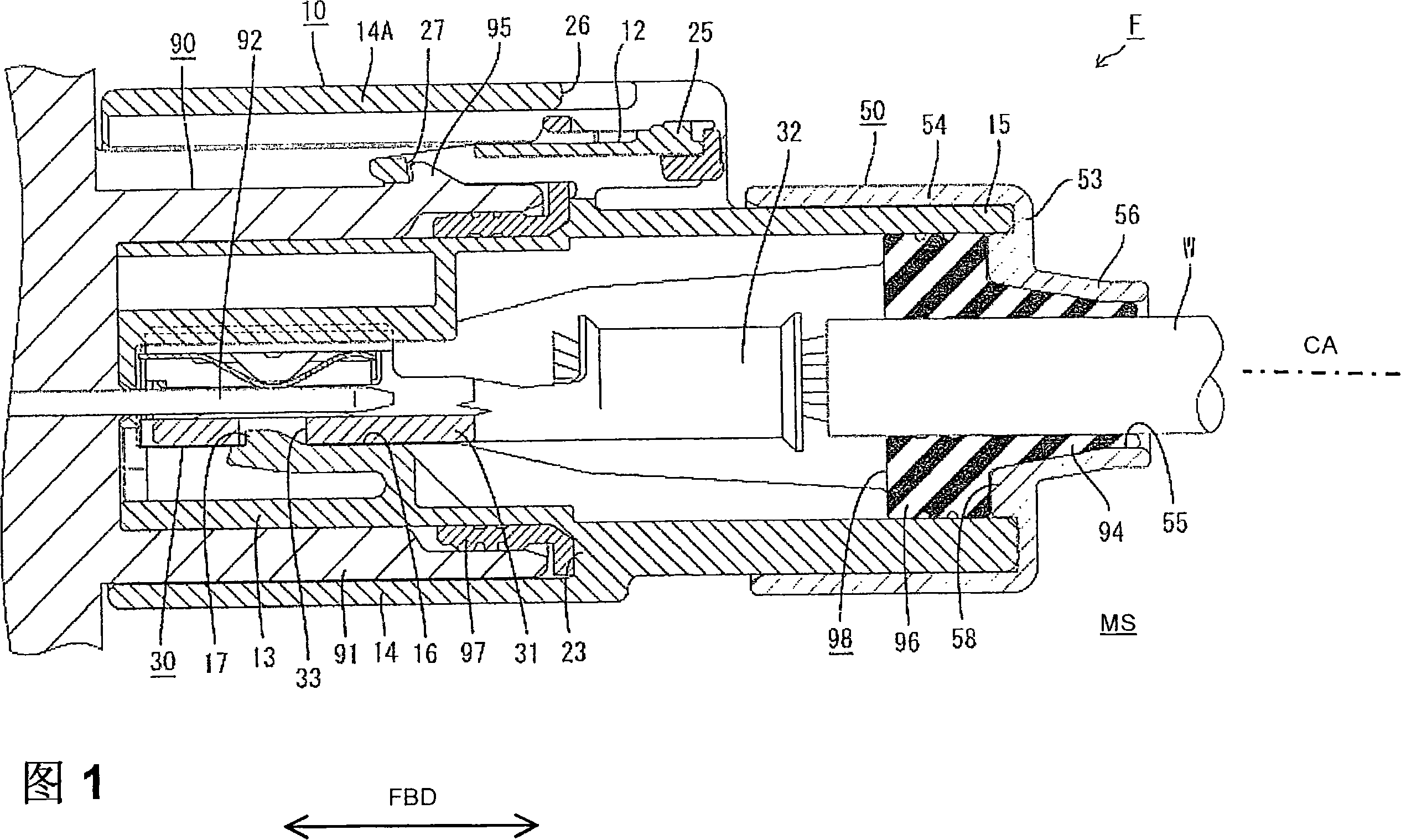
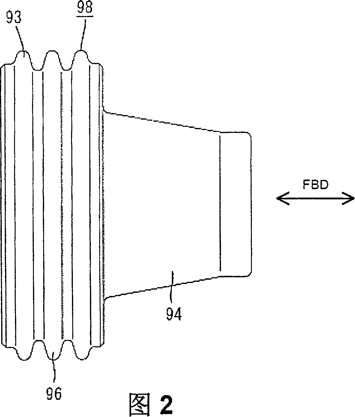
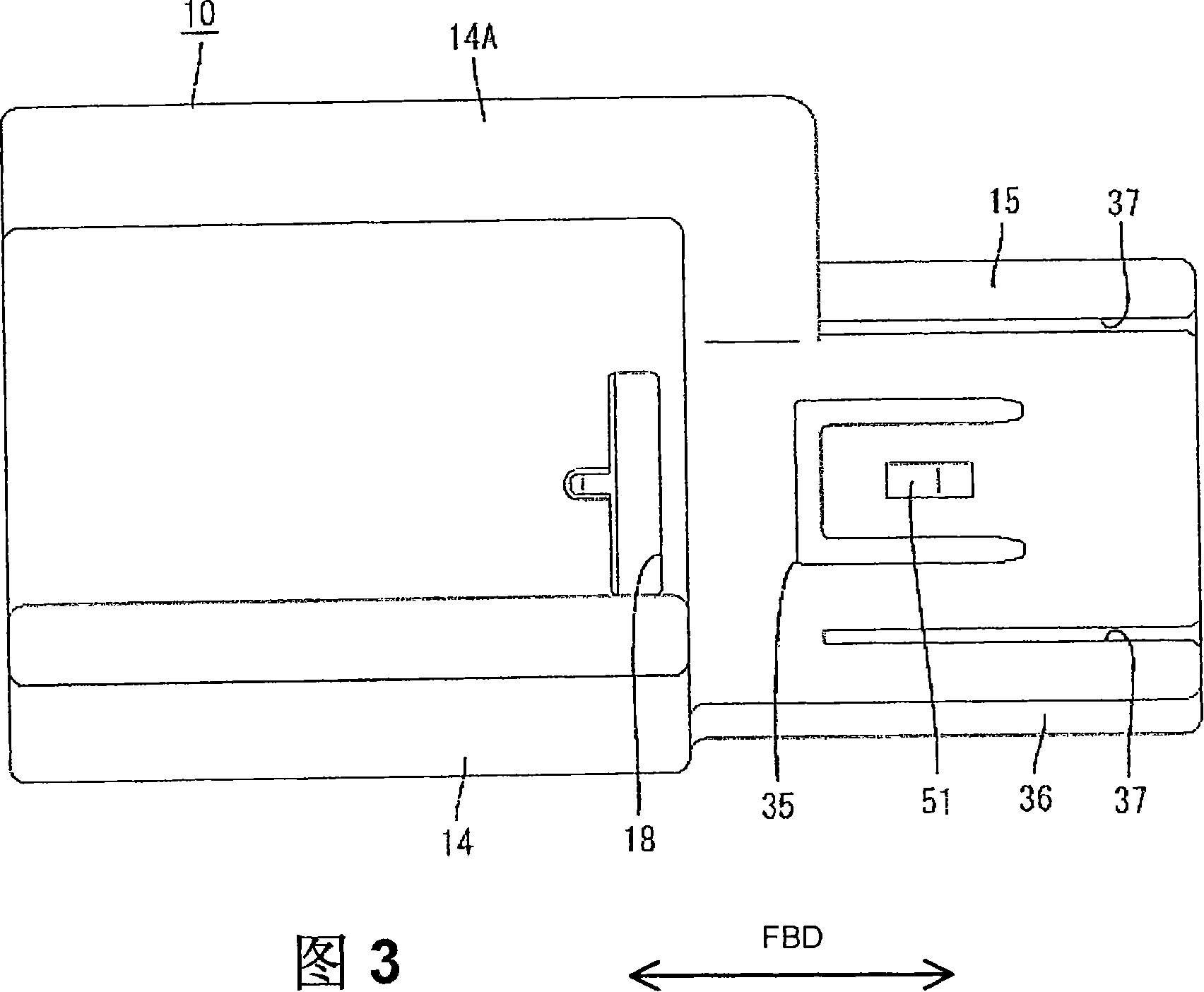
[0067] The first preferred embodiment of the present invention will be described with reference to accompanying drawings 1-7. The connector F has a female housing 10 (corresponding to a preferred connector housing) for at least partially accommodating the female terminal fitting 30 and a rear retainer 50 (as a preferred retainer) which is viewed from the mounting side The MS is mounted on the female housing 10 (preferably substantially from the rear or from a side substantially opposite to the mating side of the mating connector), wherein the female housing 10 can be connected to the mating male connector 90 . The connector F further has a sealing member 98 for providing a fluid- or waterproof seal between the female housing 10 and the terminal fitting 30 and a sealing ring 97 for providing a fluid- or waterproof seal between the female and male housings 10 and 90 . In the following description, the side to be connected of the female and male housings 10 , 90 is referred to a...

no. 2 example

[0102] A second preferred embodiment of the present invention is described with reference to FIGS. 8 to 21 . The connector F has a female housing 110 for at least partially accommodating at least one female terminal fitting 130 and a rear retainer 150 mounted on the female housing 110 from the mounting side MS (preferably substantially from the rear) (as a preferred holder), wherein the female housing 110 can be connected with a mating male housing 190. Connector F is also provided with: detection part 199 is used for detecting the connection state of female and male shell 110,190, and sealing part 198 is used for providing liquid or waterproof sealing between female shell 110 and terminal joint 130, and sealing ring 197 is used for to provide a liquid or watertight seal between the female and male housings 110 and 190. In the following description, the side to be connected of the female and male housings 110 , 190 is referred to as the front side in terms of the forward and ...


PUM


Abstract

An object of the present invention is to improve the connection reliability of a terminal fitting. A connector F is provided with a female housing 10 for accommodating a terminal fitting 30 connected with an end of a wire W, a sealing member 98 for sealing the inside of the female housing 10 by being mounted on the wire W and fitted into a mounting portion 15 as an opening portion formed in the rear surface of the female housing 10, and a rear holder 50 formed with a wire insertion hole 55, through which the wire W is inserted, and adapted to press the sealing member 98 to prevent the sealing member 98 from coming out by being mounted on the female housing 10 from behind. In the sealing member 98, a seal main body 96 to be held in close contact with the outer circumferential surface of the wire W and the inner circumferential surface of the mounting portion 15 and a shake preventing portion 94 to be held in close contact with the outer circumferential surface of the wire W and the inner circumferential surface of the wire insertion hole 55 of the rear holder 50 are arranged one after the other in forward and backward directions.

Description

technical field [0001] The invention relates to a connector. Background technique [0002] Known connector has: be used for accommodating the connector housing of the terminal fitting that is connected with an end of wire; Be installed on the wire and the sealing member that fits into opening part at the rear end of connector housing; A rear retainer on the connector housing to press and hold the sealing member (for example, see Japanese Unexamined Patent Publication No. 2004-171831). The rear holder forms a wire insertion hole through which the wire is passed, and the wire is drawn out from the wire insertion hole from the wire insertion hole. Also, the rear retainer forms an elastically deformable locking piece engageable with an engaging portion provided on the peripheral surface of the connector housing. When the rear retainer is properly mounted on the connector housing, the locking piece elastically engages with the engagement portion to clamp the rear retainer on th...

Claims


Application Information

Patent Timeline
Patent Type & Authority Applications(China)
IPC IPC(8): H01R13/52
Inventor 深谷知由田中努
Owner SUMITOMO WIRING SYST LTD
Why Eureka
Try Eureka