Hydraulic tensioner

A tensioner, hydraulic technology, applied in belt/chain/gear, mechanical equipment, transmission, etc., can solve the problems of high manufacturing cost, difficult setting, and inability to maintain the high-pressure state of the housing 510

Active Publication Date: 2006-05-10
TSUBAKIMOTO CHAIN CO
View PDF1 Cites 12 Cited by
  • Summary
  • Abstract
  • Description
  • Claims
  • Application Information

AI Technical Summary

Problems solved by technology

[0005] However, the hydraulic tensioner 500 of the prior art disclosed in the above-mentioned JP-A-2001-21011 is configured such that the air mixed in the housing 510 passes through the inner peripheral surface of the plunger 520 and the pressure overflows. The gap between the valve assembly 540 and the outer peripheral surface of the air release disk 550 is discharged from the front end of the plunger 520 to the outside of the tensioner through the helical groove 551 formed on the air release disk 550, so the It is extremely difficult to set the optimal gap between the bottom surface of the front end of the plug 520 and the spiral groove 551, which is sufficient for the mixed air to circulate moderately. The body 510 is loaded to form a valve mechanism, so for example, when the excessively pushed back plunger 520 requires a high pressure state in the case 510, the high pressure oil in the case 510 may flow out of the tensioner excessively and cannot The problem of maintaining the high-pressure state in the housing 510, in addition, because it must be installed as a separate body in the manufacturing process of the pressure relief valve assembly 540 and the air release plate 550 or in the assembly process to the housing 510, the manufacturing cost High, there are also problems in the assembly of the hydraulic tensioner 500

Method used


Image

  • Hydraulic tensioner
  • Hydraulic tensioner
  • Hydraulic tensioner

Examples


Embodiment Construction

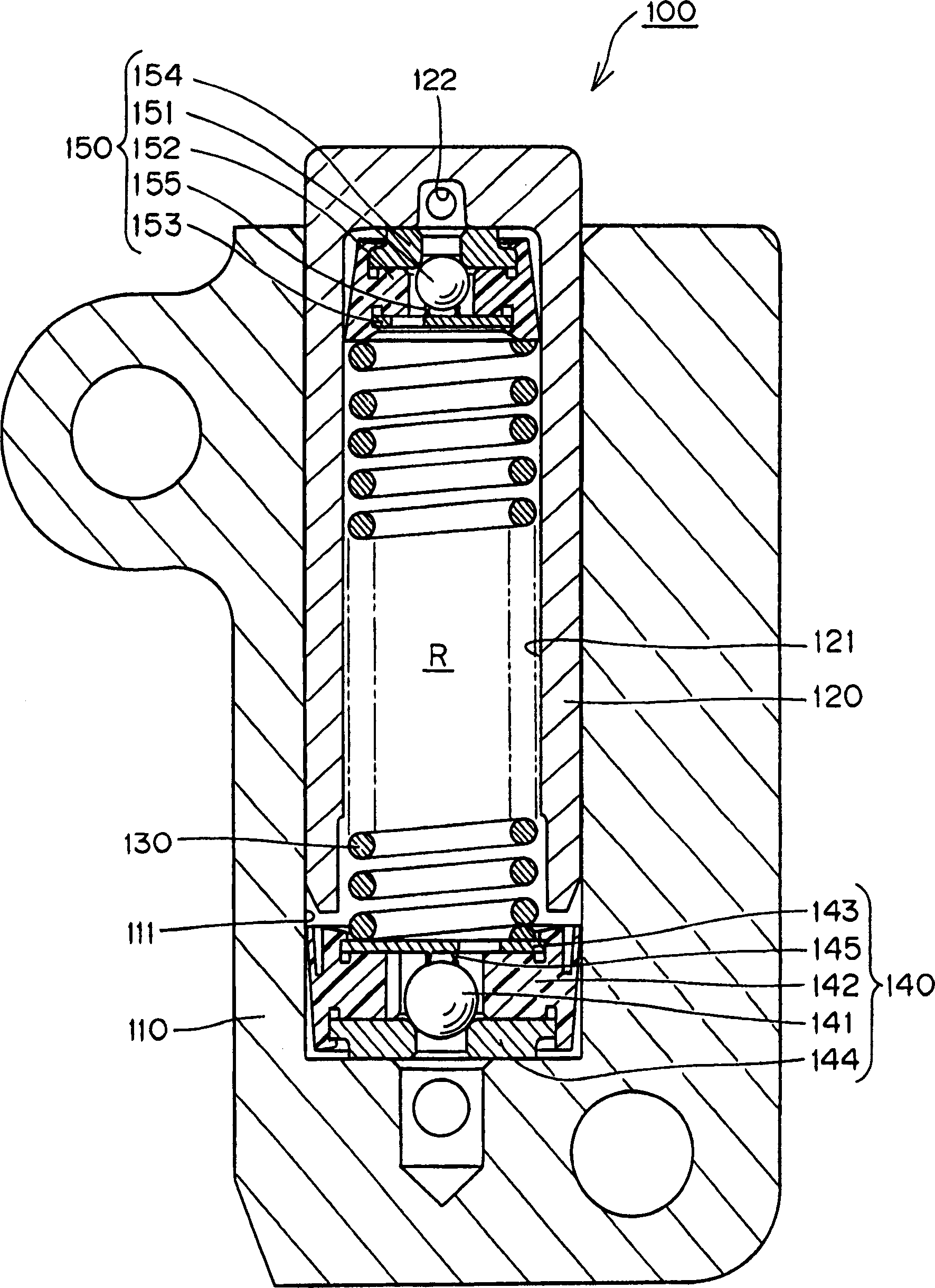
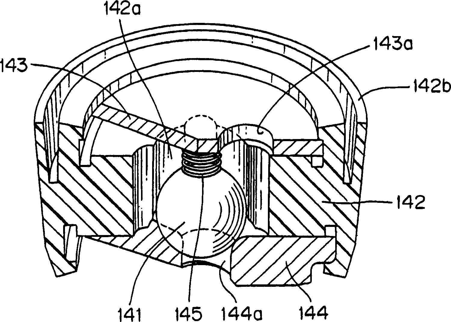
[0028]The hydraulic tensioner of the present invention is characterized in that it is equipped with a one-way ball valve that prevents the outflow of the pressure oil in the high-pressure oil chamber to extract the air mixed with it, and a ball guide that moves around the one-way ball valve in the state of enclosing the one-way ball valve. The disc-shaped baffle, which is fixed to the ball guide and seals the one-way ball valve in the ball guide, is fixed on the aforementioned ball guide to prevent the pressure oil in the high-pressure oil chamber when the one-way ball valve is in place. The ball seat that flows out of the ball seat, and the ball valve unit that loads the ball valve on the ball seat to the one-way ball valve are loaded with a spring. As long as it is easy to maintain the high pressure state in the housing body, only the negative pressure state is in the housing body. When it is easy to extract the mixed air mixed into the main body of the housing, and the parts...


PUM


Abstract

It is easy to maintain the high-pressure state in the case body, and the air mixed in the case body can be easily exhausted only when the case body becomes a negative pressure state, and the case can be easily and firmly installed. A hydraulic tensioner with excellent durability of parts in the main body. The exhaust valve unit of the hydraulic tensioner (100) consists of a one-way ball valve (151) that prevents the outflow of pressure oil in the high-pressure oil chamber (R) and exhausts the mixed air, and includes the one-way ball valve (151 ) state to make the ball guide (152) to swim, fix on the ball guide (152), seal the one-way ball valve (151) in the disc-shaped baffle in the ball guide (152) (153), the ball seat (154) that is fixed on the ball guide (152), stops the outflow of the pressure oil in the high-pressure oil chamber (R) when the one-way ball valve (151) is in place, and to the ball seat ( 154) The ball valve loading of the one-way ball valve (151) is loaded with a spring (155).

Description

technical field [0001] The present invention relates to a hydraulic tensioner for applying appropriate tension to, for example, a timing belt or a timing chain of a vehicle engine. Background technique [0002] Generally speaking, on the timing belt or timing chain that transmits rotation between the crankshaft and camshaft of the vehicle engine, a hydraulic type with a spherical check valve mechanism that suppresses vibration caused by tension changes during travel is widely used. tensioner. [0003] Conventionally, as such a hydraulic tensioner equipped with a spherical check valve mechanism, a spring is provided to bias a hollow plunger 520 slidably inserted into a hole of the housing 510 in a protruding direction, and a spring is provided on the plunger. The inside of the plunger 520 is integrated into the pressure relief valve assembly 540 on the front end side and the air release disc 550, and the air mixed in the housing 510 is discharged out of the tensioner through...

Claims


Application Information

Patent Timeline
Patent Type & Authority Applications(China)
IPC IPC(8): F16H7/08
CPCF16H7/0836F16H2007/0806F16H2007/0812F16H2007/0817F16H2007/0853F16H2007/0859F16H2007/0891
Inventor 吉田修三宅浩行
Owner TSUBAKIMOTO CHAIN CO
Why Eureka
Try Eureka