Connector

a technology of connecting rods and connecting rods, applied in the direction of coupling device connection, coupling base/case, securing/insulating coupling contact members, etc., can solve the problems of affecting the reliability of connection, wires in the housing shaking, etc., to prevent detachment of the holder, facilitate the alignment of the internally disposed leading-end, and mount precisely and efficiently on the mounting portion

Inactive Publication Date: 2008-01-03
SUMITOMO WIRING SYST LTD
View PDF10 Cites 12 Cited by
  • Summary
  • Abstract
  • Description
  • Claims
  • Application Information

AI Technical Summary

Benefits of technology

[0017]The leading-end widened rib or the recess at the inner surface of the surrounding wall of the holder preferably extends substantially to the back wall of the holder to further prevent detachment of the holder.
[0018]The surrounding wall of the holder preferably is substantially cylindrical and the leading-end widened rib is provided on the inner circumferential surface of the surrounding wall. The leading-end widened rib may not be readily visible during mounting of the holder in view of the internal disposition of the leading-end widened rib. Accordingly, a recessed groove is formed in the outer circumferential surface of the surrounding wall at a position substantially radially aligned with the leading-end widened rib to define a back-to-back relationship. The recessed groove defines a marker to facilitate alignment of the internally disposed leading-end widened rib with the recess. As a result, the holder can be mounted precisely and efficiently on the mounting portion. Further, the disposition of the recessed groove back-to-back with the leading-end widened rib avoids an increase in the thickness of the surrounding wall and prevents an occurrence of a surface sink. Furthermore, the internal disposition of the leading-end widened rib assures that the leading-end widened rib will not be caught by external matter and broken.

Problems solved by technology

However, the wire drawn out of the housing can be shaken in this state and can cause the wire in the housing to shake within the range of a clearance between the wire and the wire insertion hole.
As a result, the terminal fittings might slide in contact with each other, and connected positions of both terminal fittings can change to impair connection reliability.

Method used


Image

  • Connector
  • Connector
  • Connector

Examples


first embodiment

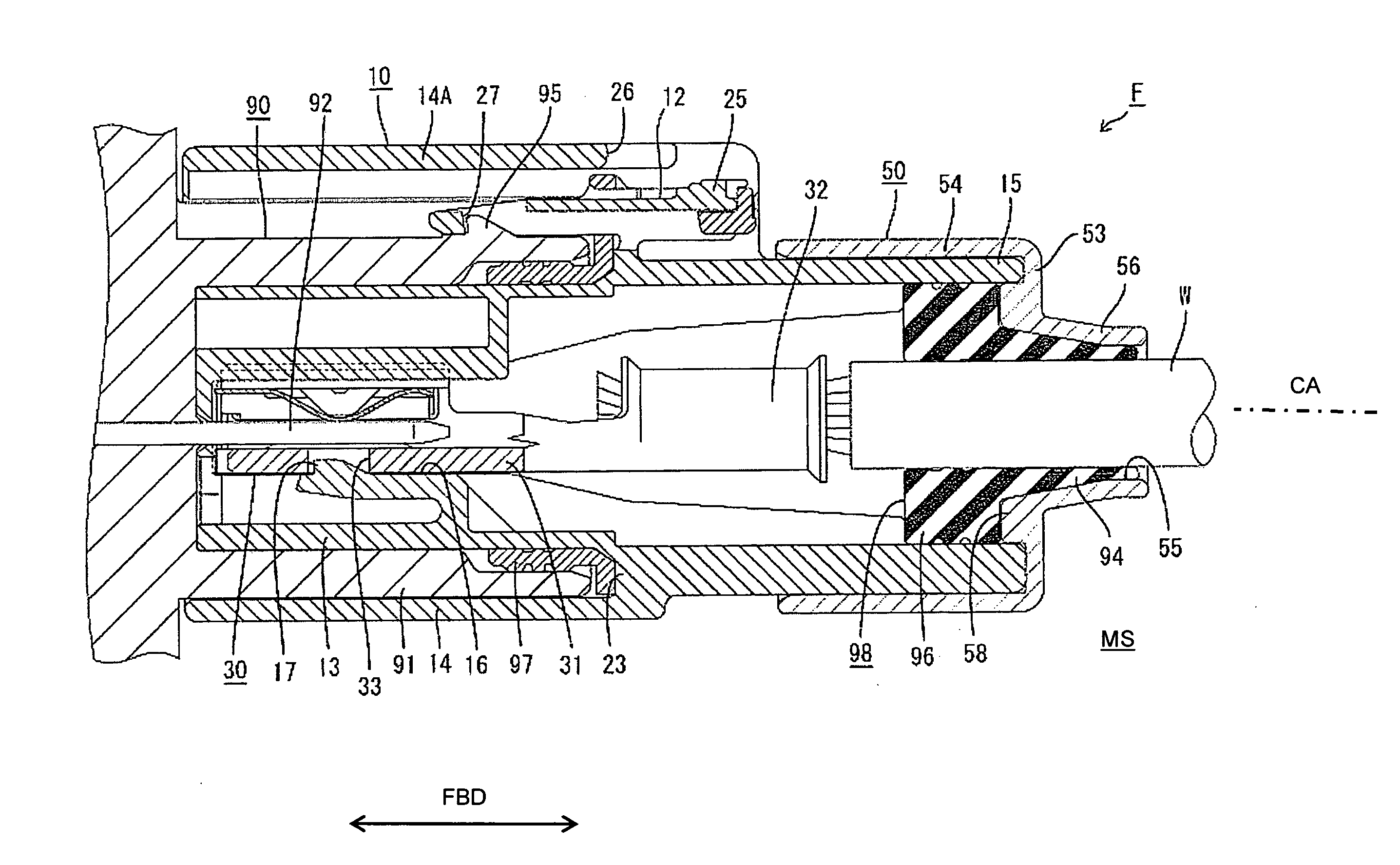
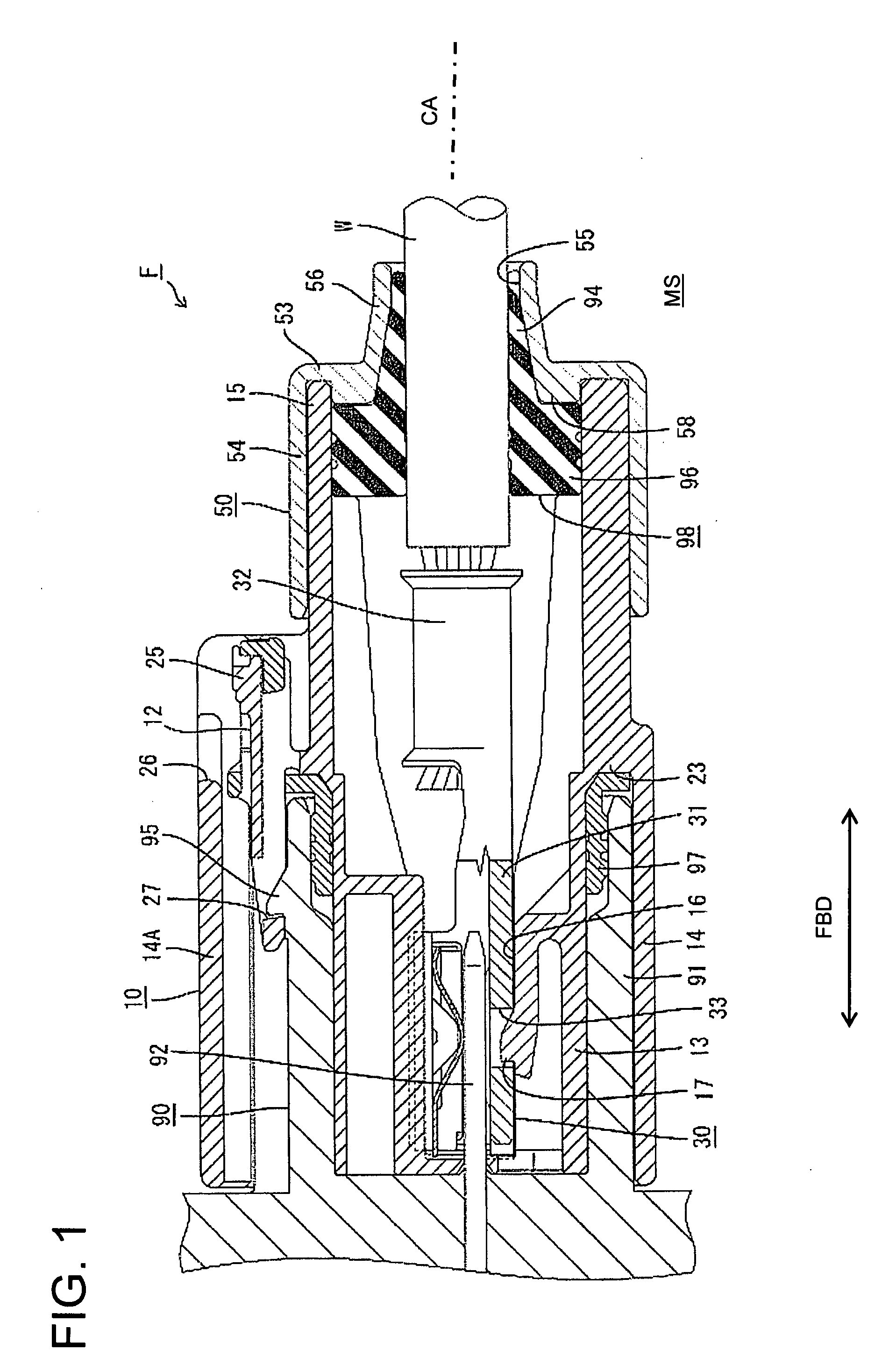
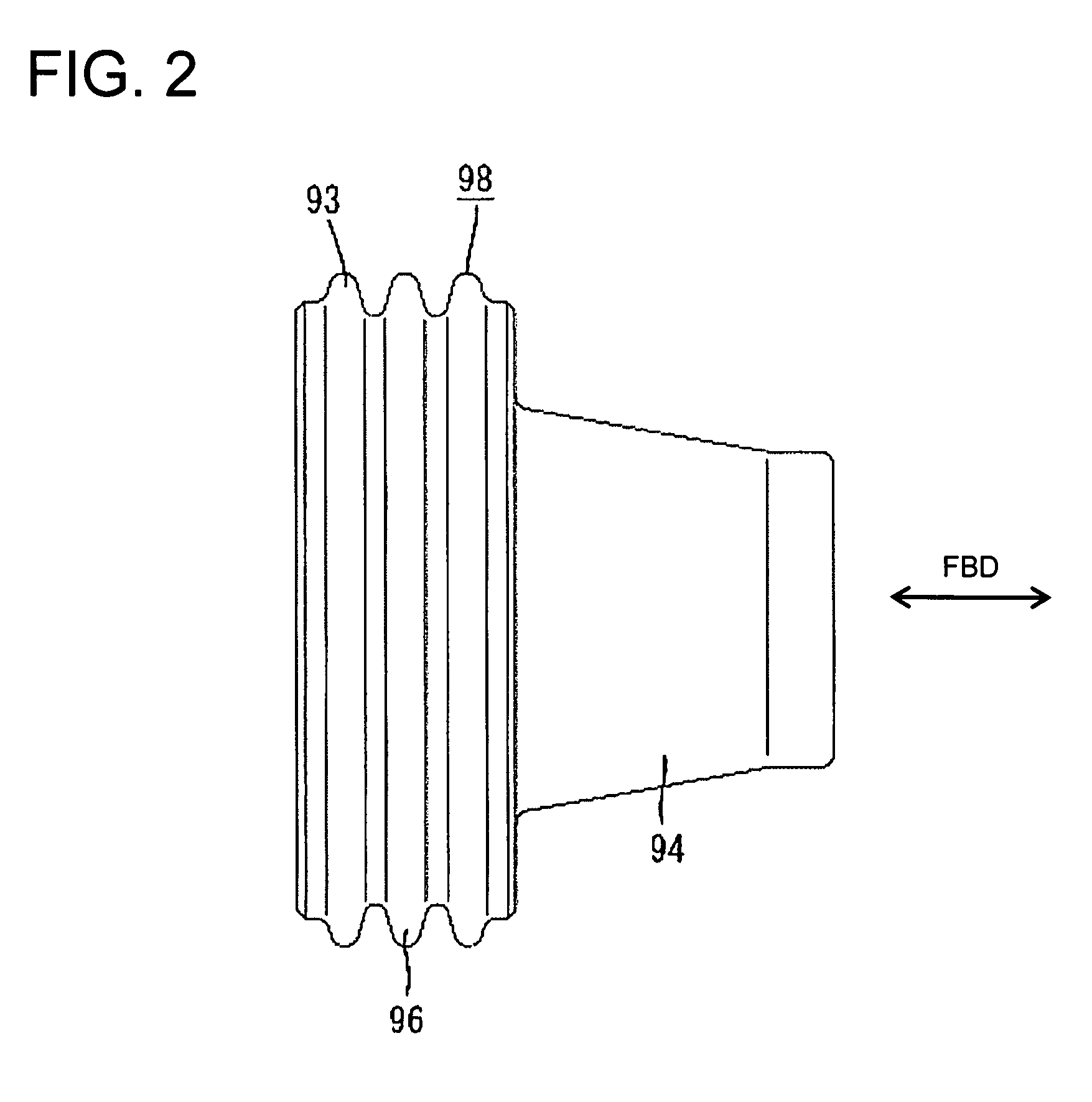
[0042]A connector in accordance with the invention is identified by the letter F in FIGS. 1 to 7. The connector F has a female housing 10 for accommodating a female terminal fitting 30 and a rear holder 50 to be mounted on the female housing 10 from a mounting side MS. The female housing 10 is connectable with a mating male housing 90. The connector F further has a seal 98 for providing fluid- or waterproof sealing between the female housing 10 and the terminal fitting 30 and a seal ring 97 for providing fluid- or waterproof sealing between the female and male housings 10 and 90. Ends of the female and male housings 10, 90 to be connected are referred to herein as the front ends concerning forward and backward directions FBD and reference is made to FIG. 1 concerning the vertical direction.

[0043]The mating male housing 90 is made e.g. of a synthetic resin and includes a round tubular receptacle 91 having an open front end. One male tab 92 is mounted through the back wall of the rece...

second embodiment

[0070]A connector according to the invention is identified by the letter F in FIGS. 8 to 21. The connector F has a female housing 110 for accommodating a female terminal fitting 130 and a rear holder 150 to be mounted on the female housing 110 from a mounting side MS. The female housing 110 is connectable with a mating male housing 190. The connector F also has a detector 199 for detecting a connected state of the female and male housings 110, 190. In the following description, ends of the female and male housings 110, 190 to be connected are referred to as the front ends concerning forward and backward directions FBD and reference is made to FIG. 8 concerning the vertical direction.

[0071]The mating male housing 190 is made of a synthetic resin and includes a round tubular receptacle 191 with an open front end, as shown in FIG. 21. A male tab 192 is mounted through the back wall of the receptacle 191 and projects into the receptacle 191. The male tab 192 is a plate made of an electr...


PUM


Abstract

A connector (F) has a housing (10) for accommodating a terminal fitting (30) connected with wire (W). A seal (98) is mounted on the wire (W) and fits in a mounting portion (15) in the rear of the housing (10). A holder (50) is mounted on the housing (10) from behind to press the seal (98) and to prevent the seal (98) from coming out. The holder (50) has a wire insertion hole (55) for receiving the wire (W). The seal (98) has a main body (96) and a shake preventing portion (94). The main body (96) closely contacts the outer surface of the wire W and the inner surface of the mounting portion (15). The shake preventing portion (94) closely contacts the outer surface of the wire (W) and the inner surface of the wire insertion hole (55) of the holder (50).

Description

BACKGROUND OF THE INVENTION[0001]1. Field of the Invention[0002]The invention relates to a connector.[0003]2. Description of the Related Art[0004]U.S. Pat. No. 6,887,106 discloses a connector with a housing for accommodating a terminal fitting connected with an end of a wire. A sealing member is mounted on the wire and is fit into an opening at the rear end of the housing. A rear holder is mounted on the housing from behind to press and retain the sealing member. The rear holder is formed with a wire insertion hole through which the wire is passed, and the wire is drawn out to the outside through the wire insertion hole. The rear holder also is formed with a resiliently deformable locking piece that is engageable with an engaging portion on the circumferential surface of the housing. The locking piece engages the engaging portion when the rear holder is mounted properly on the housing to retain the rear holder on the housing.[0005]The above-described connector is connected with a ma...

Claims


Application Information

Patent Timeline
Patent Type & Authority Applications(United States)
IPC IPC(8): H01R13/40
CPCH01R13/506H01R13/6272H01R13/5208H01R13/639
Inventor FUKAYA, TOMOYOSHITANAKA, TSUTOMU
Owner SUMITOMO WIRING SYST LTD
Why Eureka
Try Eureka