
Liquid-controlled type multi-purpose valve

A multi-purpose valve and hydraulic control technology, applied in the direction of multi-way valve, lift valve, valve details, etc., can solve the problems of large product volume, unfavorable product competition, and insufficient spring force stability

Inactive Publication Date: 2008-02-20
生贵阀门有限公司
View PDF0 Cites 0 Cited by
  • Summary
  • Abstract
  • Description
  • Claims
  • Application Information

AI Technical Summary

Problems solved by technology

Whether it is an open valve or an air-closed valve, it is reset by a spring, but this structure of the valve has the following disadvantages: 1. The spring force is not stable enough, and it will often change after a long time; 2. Working noise Large, large vibration, especially large-scale valves need to install more than two springs in order to ensure the elastic force, so the mutual friction sound is also very loud, and the springs affect each other to change the elastic force; 3. This kind of valve needs space to accommodate the springs Large, so the cylinder will be long, and the volume of the whole product will be large; 4. The spring must have a guide device, otherwise the spring is easy to bend and affect the elastic force; Competition; 6. Springs made of carbon steel are prone to rust, while springs made of stainless steel are not elastic enough and the cost is very high

Method used


Image

  • Liquid-controlled type multi-purpose valve
  • Liquid-controlled type multi-purpose valve
  • Liquid-controlled type multi-purpose valve

Examples


Embodiment Construction

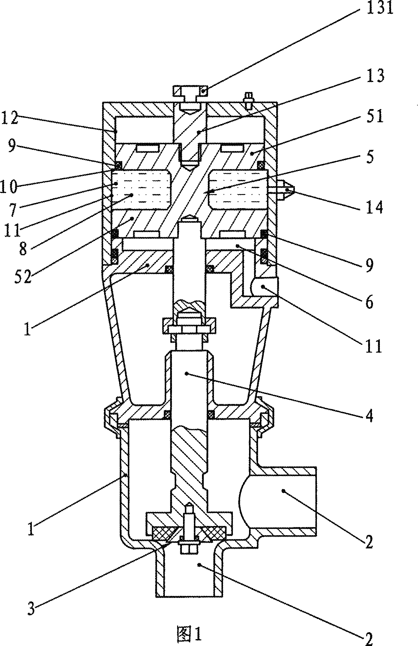
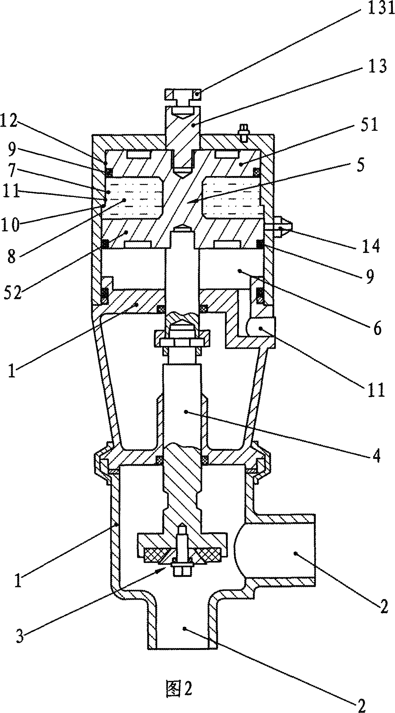
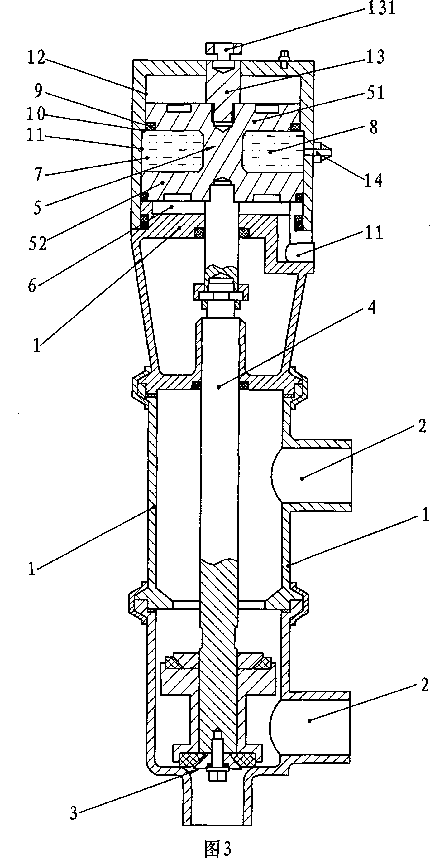
[0011] As shown in the figure, a hydraulically controlled multi-purpose valve includes a valve body 1, a flow channel 2 arranged in the valve body 1, a valve core device 3 that cooperates with the flow channel 2, and a valve core device 3 linked with the valve core device. The valve stem 4 and the piston 5 that controls the sliding of the valve stem 4. What needs to be explained here is the spool device 3, which is a device for controlling the flow of the flow channel 2 or controlling the on-off of the flow channel 2. One side of the piston 5 is set There is a sealed cavity 6, and the valve body 1 is provided with an air inlet and outlet channel 11 connected with the cavity 6, through which the gas pressure in the cavity 6 can be controlled and adjusted to realize the internal pressure change; in the embodiment of the present invention, a closed cavity 7 is additionally provided between the piston 5 and the valve body 1, and the cavity 7 is filled with a liquid 8, and the cavit...


PUM


Abstract

The invention relates to a valve, in particular to a hydraulically-controlled multifunction valve, the piston of which adopts the hydraulic control system. The invention adopts the following technical proposal: the hydraulically-controlled multifunction valve includes a valve body, a passage arranged inside the valve body, a valve plug device matching with the passage, a valve stem connected with the valve plug and a piston which controls the slide of the valve stem. A sealed cavity is arranged at one side of the piston, an inlet air passage and an outlet air passage which are communicated with the cavity are arranged on the valve body; the invention is characterized in that a sealed cavity is additionally arranged between the piston and the valve body and the sealed cavity is filled with liquid, the volume of the cavity changes with the slide of the piston, the volume change mode is contrary to the volume change of the sealed cavity at the side of the piston; with the technical proposal, the invention overcomes the defects of the prior art and provides a new hydraulically-controlled multifunction valve which is simple in structure, stable in performance, convenient to manufacture and low in cost.

Description

technical field [0001] The invention relates to a valve, in particular to a hydraulically controlled multipurpose valve whose piston is controlled by hydraulic pressure. Background technique [0002] At present, the existing valves close to the present invention include a valve body, a flow channel arranged in the valve body, a valve core device that cooperates with the flow channel to realize flow channel change or on-off, and a valve that is linked to the valve core device. The rod and the piston that controls the sliding of the valve rod. The two sides of the piston are respectively a spring and a sealed cavity that can change the gas pressure. For the valve with this structure, the linear movement of the piston is based on the air pressure and spring force on both sides. The opening and closing or reversing of the valve is achieved by the alternating action of the valve. The opening and closing or reversing mentioned here are for different valves. When it is a cut-off va...

Claims


Application Information

Patent Timeline
Patent Type & Authority Applications(China)
IPC IPC(8): F16K1/00F16K31/122F16K11/044
Inventor 沈汉民
Owner 生贵阀门有限公司
Learn More